


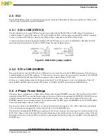
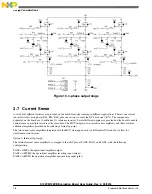

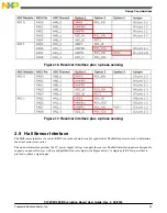


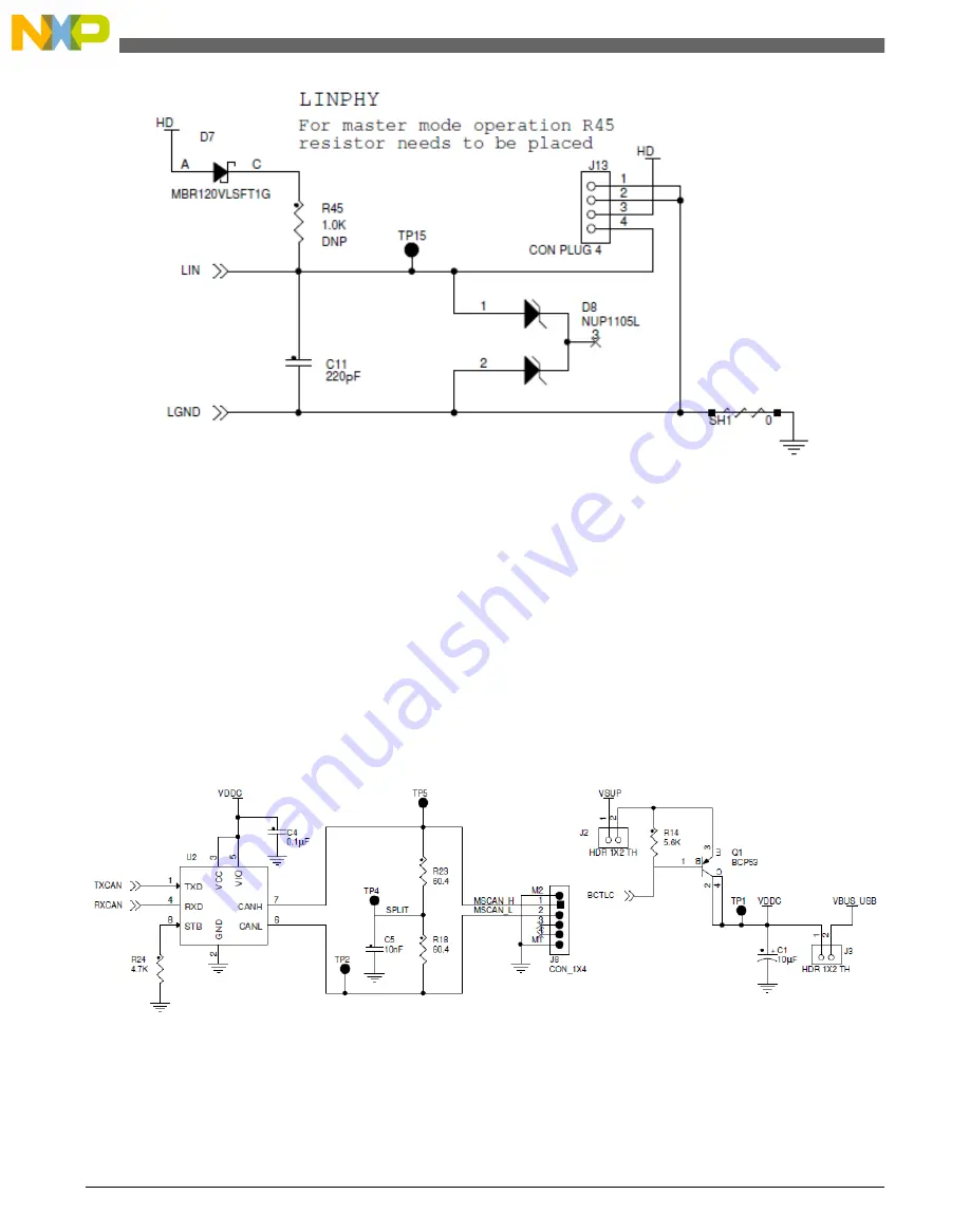
Figure 7. LIN interface
3.4.3 CAN Transceiver
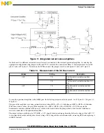
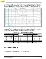
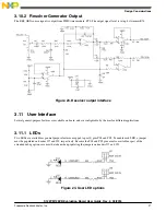
The EVB includes an external CAN transceiver that can be linked to the MSCAN module of the S12ZVM device, by
populating the appropriate resistors as shown in
.
In the CAN version of the EVB, the external transceiver can be powered by a voltage regulator controlled by the
S12ZVMC12 microcontroller. An external PNP BJT ballast transistor is required to deliver regulated 5 V to the CAN
transceiver. The base of the transistor must be connected to the BCTLC base control pin on the microcontroller. The collector
of the transistor must be connected to the VDDC pin on the microcontroller. A 5.6 kiloohm resistor is recommended from the
base to the emitter of the transistor. The emitter terminal must be supplied from the VSUP (reverse polarity protected) battery
supply. A jumper must be populated on header J2 to enable the supply to the transistor. The jumper on header J3 must not be
populated in this case.
Figure 8. CAN Transceiver
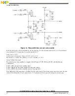
In the LIN version of the EVB, the microcontroller can’t control the ballast transistor, because the VDDC and BCTLC pins
are replaced by the LIN and LGND pins of the LIN physical layer. However, the MSCAN module in the microcontroller can
still be linked to the external CAN transceiver. The transceiver 5 V supply can be powered from the USB connector, J25, as
long as a jumper is populated on header J3. In this case, the jumper on header J2 must be removed.
Design Considerations
S12ZVM12EVB Evaluation Board User Guide, Rev. 2, 03/2016
16
Freescale Semiconductor, Inc.