


NXP Semiconductors
UM11192
User Manual for LPCXpresso54S018M Development Board
UM11192
All information provided in this document is subject to legal disclaimers.
© NXP B.V. 2019. All rights reserved.
User manual
Rev. 1.0
— 13th February 2019
29 of 34
(1)
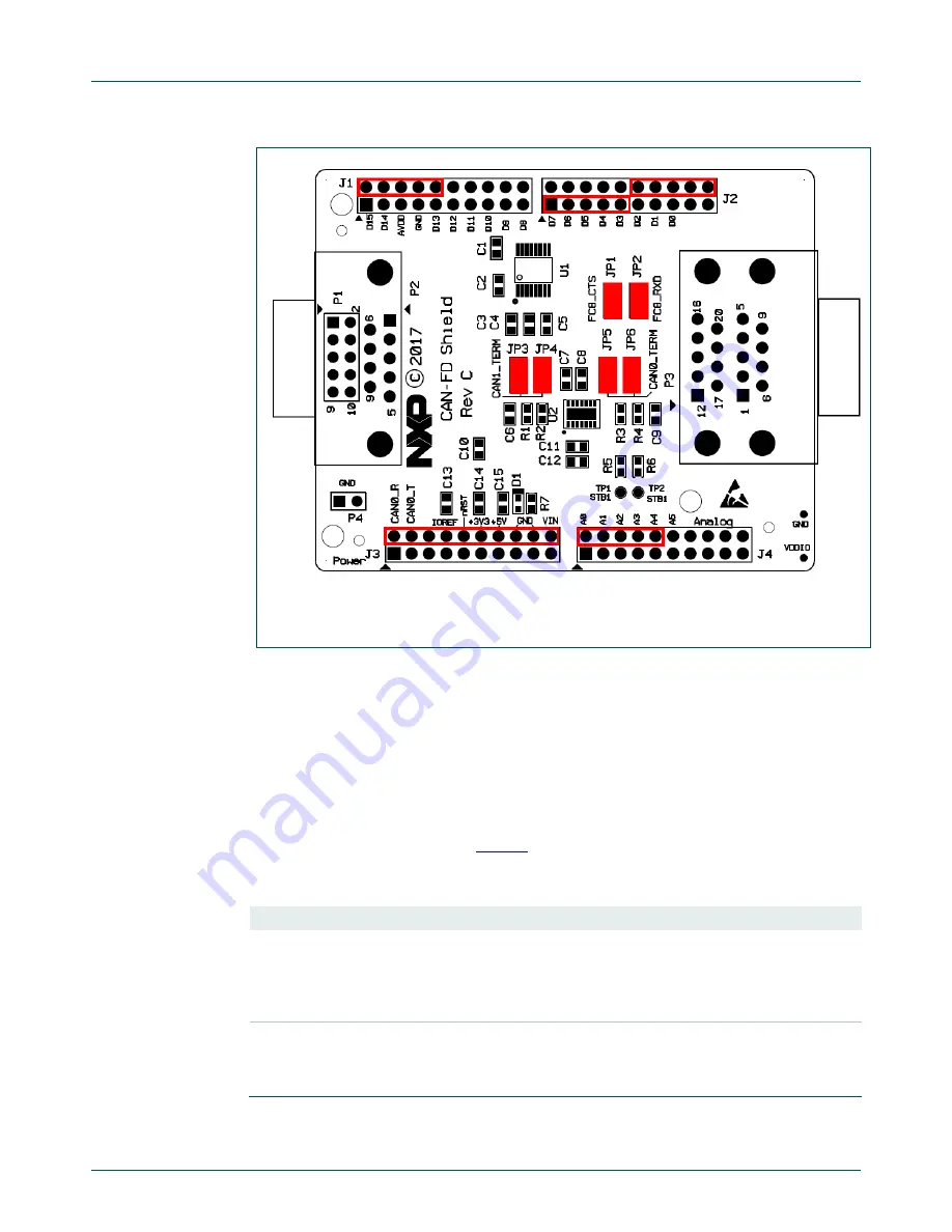
Fig 9.
CAN-FD Shield Layout
The CAN-FD Shield has a double-height DB9 connector installed by default (P3) for
CAN/CAN-FD connections.
The Shield board layout includes provision for a DB9 connector to be installed (P2) but a
standard 0.1” header (P1) is installed by default; P1 would need to be unsoldered in
order for P2 to be fitted.
Note that header P4 is provided to allow convenient access to ground.
11.2 Jumper settings
Jumper settings are described in
Table 8
.
Table 8.
CAN-FD Shield Jumper settings
Circuit ref
Description
Default
JP1
RS232C transceiver CTS connection.
When fitted, the RS232C transceiver CTSn signal is connected
to expansion connector J4 pin 8 (Arduino A4). On the
LPCXpresso54S018M boards A4 is connected to pin PIO3_4;
this pin is shared with the accelerometer interrupt output.
Installed
JP2
RS232C transceiver RXD connection.
When fitted, the RS232C transceiver R1OUT signal is connected
to expansion connector J2 pin 20. On the LPCXpresso54S018M
boards A4 is connected to pin PIO2_17.
Installed