


NXP Semiconductors
KTFRDM34933EVBUG
FRDM-34933EVB evaluation board
KTFRDM34933EVBUG
All information provided in this document is subject to legal disclaimers.
© NXP B.V. 2017. All rights reserved.
User guide
Rev. 1.0 — 15 March 2017
32 / 39
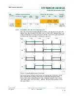
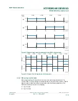
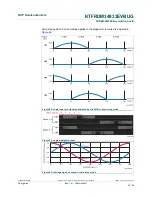
Figure 21. Signals of logic input pins generated by the MCU in full-step mode
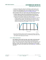
Figure 22. Output of the H-bridge device in full-step mode
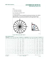
6.6.2 Micro-step control mode
Micro-stepping allows for smoother motor movement and increased precision. The
current varies in motor windings A and B depending on the micro-step position. A PWM
signal is used to reach the desired current value (see the following equations). This
method is called sine cosine micro-stepping.
I
A
= I
MAX
X sin(θ)
I
B
= I
MAX
X cos(θ)