


NXP Semiconductors
KTFRDM34933EVBUG
FRDM-34933EVB evaluation board
KTFRDM34933EVBUG
All information provided in this document is subject to legal disclaimers.
© NXP B.V. 2017. All rights reserved.
User guide
Rev. 1.0 — 15 March 2017
22 / 39
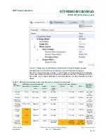
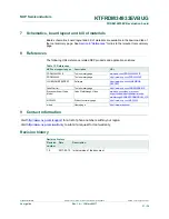
6.5.4 Setting up a project to control a stepper motor
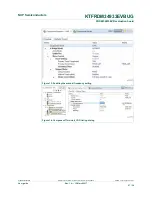
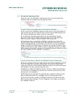
Select the dual H-bridge model you want to configure and set Stepper in the Motor
Control property. Note that the dual H-bridge model is required, because a two phase
bipolar stepper motor has four inputs.
Figure 10. Component settings to control a stepper motor
In the Stepper Motor group, set the properties that apply to your environment.
•
The Output Control property defines the control method.
–
With PWM selected the component utilizes four channels of a timer to control
the stepper motor. Signal is generated in hardware and micro-step mode is also
available.
–
In GPIO mode, GPIO pins are used instead of timer channels and only full-step mode
is available (no micro-step mode).
•
Manual Timer setting property is only visible when you switch the visibility of the
component properties to Advanced. It is designed to change the Counter frequency