


NXP Semiconductors
KTFRDM34933EVBUG
FRDM-34933EVB evaluation board
KTFRDM34933EVBUG
All information provided in this document is subject to legal disclaimers.
© NXP B.V. 2017. All rights reserved.
User guide
Rev. 1.0 — 15 March 2017
31 / 39
6.6 Stepper motor control application notes
The LVHBridge component is designed to control a two phase bipolar stepper motor.
Because a stepper motor uses electrical commutation to rotate, it requires a dual H-
bridge device. The basic control method is full-stepping which fully powers each coil
in sequence. Increased precision is achieved by using the PWM to control coil current
(open loop control). This method is called micro-stepping (available in the LVHBridge
component.)
In both micro-step and full-step mode you can control motor speed, direction,
acceleration and deceleration and the position of the stepper motor.
The following application notes apply to stepper motor control:
•
The LVHBridge component was tested with a core clock frequency ranging from 20
MHz (minimum value) to 120 MHz.
•
Do not change the settings of the timer device (TimerUnit_LDD) linked by the
LVHBridge component. The component sets the timer device automatically.
•
The acceleration and deceleration ramp of the stepper motor is computed in real-time
using integer arithmetic. This solution is based on the article "Generate stepper-motor
speed profiles in real time" (Austin, David. 2005.)
•
The stepper motor holds its position (coils are powered) after motor movement is
completed. Use method DisableMotor to set H-bridge outputs to LOW (coils are not
powered).
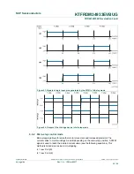
•
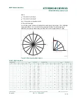
Forward motor direction indicates that steps are executed in the order depicted in
Figure 21
. IN1 through IN4 are the input pins of the H-bridge device which control H-
bridge outputs. These pins input to the stepper motor. You must connect the stepper
motor to output pins OUT1-OUT4 and select control input pins on your MCU in the
component settings.
•
The FTM or TPM timer device is needed by the stepper control logic.
•
The AlignRotor method affects the position of the motor. This method executes four
full-steps. It is available only when full-step mode is enabled.
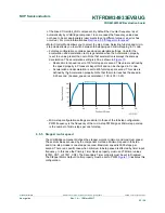
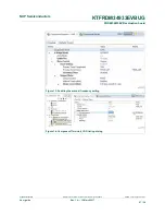
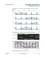
6.6.1 Full-step control mode
The component uses normal drive mode where two coils are powered at the same time.
As mentioned in
Section 6.5.4 "Setting up a project to control a stepper motor"
, you can
generate a full-stepping signal either by using four channels of a timer or by using four
GPIO pins. The signal generated by the MCU (inputs of H-bridge device) using four timer
channels is shown in
Figure 21
. The voltage levels applied to the coils of the stepper
motor are depicted in
Figure 22
. Note that the voltage is applied to both coils at the same
time.