


NXP Semiconductors
FS4500/FS6500 evaluation boards
KTFRDMFS4500-FS6500EVMUG
FS4500/FS6500 evaluation boards
All information provided in this document is subject to legal disclaimers.
© NXP B.V. 2017. All rights reserved.
User guide
Rev. 4.0 — 12 June 2017
18 / 34
•
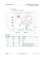
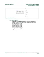
R42: populated
•
C8/C9/R4/D3/L2/C5/C7/R2/C11/R5/C17: DNP
aaa-025550
.
Figure 11. V
CORE
configuration
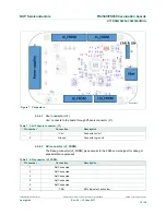
5.2.2 Compensation network
Both LDO and DC/DC voltage regulators use VCORE voltage feedback to control the
output voltage (see
Figure 12
).
For FS45xx devices using static (steady-state) LDO regulators, a simple resistor bridge
(resistors R3 and R6) determines the feedback voltage. By default, the feedback voltage
is 1.3 V.
For FS65xx devices using DC/DC voltage regulators, a pair of RC voltage dividers
controls the dynamic behavior of the regulator.
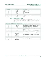
5.2.3 FCRBM Resistor Bridge
The feedback core bridge monitoring (FCRBM) Resistor Bridge is an evaluation board
safety feature.
The bridge generates the same voltage as the bridge connected to the FB_core pin. If
the difference between the two voltages is greater than the VCORE_FB_DRIFT value,
the FS state machine is impacted (refer to data sheet). The drift value is set to 1.3V by
default.