


NXP Semiconductors
FS4500/FS6500 evaluation boards
KTFRDMFS4500-FS6500EVMUG
FS4500/FS6500 evaluation boards
All information provided in this document is subject to legal disclaimers.
© NXP B.V. 2017. All rights reserved.
User guide
Rev. 4.0 — 12 June 2017
12 / 34
aaa-025547
.
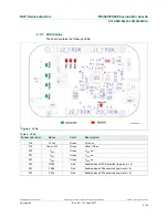
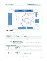
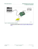
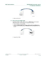
Figure 7. Connectors
4.5.4.1 V
BAT
connector (J1)
V
BAT
connects to the board through Phoenix connector (J1).
Table 7. V
BAT
Phoenix connector (J1)
Pin number
Connection
Description
1
V
BAT
Connects to V
BAT
2
Ground
Connects to ground
4.5.4.2 SPI connector (J2_FRDM)
The Debug connector(J2_FRDM) gives access to the FS65xx main signal for debug or
experimentation purposes.
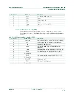
Table 8. SPI connector (J2_FRDM)
Pin number
Connection
Description
1
Not Connected
2
Not Connected
3
Not Connected
4
Not Connected
5
Not Connected
6
CSB
SPI chip select, active low