background image

23

LCD Display

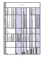
Fault

Possible Cause

Effect on Product

Investigate the Following

Action Required

If Fault  Persists

Blank

* No power

* Key switched of

f

* Emergency stop pressed

* Machine will not operate

* Key switched of

f

* Emergency stop pressed

* Switch key on

* Release emergency stop

‘OVER CURRENT’

* Brush over current

* Brush pressure too great

* Brush current exceeds 32A

* W

rong type of brush for surface

* V

ac. brush, water & 

Detergent motors / pump 

will not operate

* Brush LED’

s all flash in 

unison until the Pedal is 

released

* Release brush pressure

* Change type of brush

* Restart machine

‘UNDER VOL

TS’

* Battery 

voltage dropped  

  below 21 V

olts

* Left most battery LED flashes

* Batteries require recharging

* Faulty cell on battery

* Machine will not operate

* Battery leads and connections

* Charge batteries

* Replace battery 

(if cell damaged)

‘V

AC OVER CURRENT’

* V

acuum motor fault

* Debris entering vacuum motor

* W

ater ingress

* Machine disabled

* Restart machine

* Replace vacuum motor

‘INHIBITED’

MACHINE INHIBITED - NO OPERA

TION

Contact Service Agent

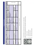
To view CRO 8055 run time information turn the key to the ‘ON’

 position.

Press the run-time information button to cycle between the dif

ferent modes.

T = 


Traction run-time

  V =


Vacuum total run-time

B =


Brush total run-time

W =


W

ater Pump total run-time

Trouble Shooting

Содержание CRO 8055/100T

Страница 1: ...Original instructions Warning Read instructions before using the machine www numatic com CRO 8055 100T CRO 8055 120T Ride On Scrubber Dryer Owner Instructions...

Страница 2: ...k full Brush pressure Emergency stop button and horn Anti tip System Machine usage advice Maximum Speed Control Hose U Bend Clip Off aisle cleaning kit optional Machine Cleaning Tanks and Filters Floo...

Страница 3: ...Accelerator pedal 3 Anti tip buffers 12 Pedestrian warning light 4 Floor tool raise lower lever 13 Floor tool transit bracket 5 Clean water tank fill point 14 Air separator assembly 6 Brush deck 15 W...

Страница 4: ...n 3 Service Indicator 4 Brush Pressure Load Indicator 5 Run Time Selection Button 6 Battery Charge Level Indicator 7 Off Aisle Vacuum Button 8 On Off Switch 9 Forward Reverse Switch 10 LED Status Indi...

Страница 5: ...er dryer into household waste According to the European Directive 2002 96 EC on waste electrical electronic equipment and its incorporation into national law Scrubber dryers that are no longer suitabl...

Страница 6: ...brushes provided with the appliance or those specified in the instruction manual The use of other brushes may impair safety A full range of brushes and accessories are available for this product Only...

Страница 7: ...the speed control is set to low Fig 4 DO NOT depress accelerator pedal while software initialises Depress accelerator pedal with right foot and slowly drive machine off of the pallet using the ramp pr...

Страница 8: ...or tool move the floor tool lever into the upper position Fig 7 9 To raise the floor tool move the floor tool lever into the lower position Fig 8 Note The machine will not operate in reverse with the...

Страница 9: ...a quarter turn clockwise Press the brush engage button and the machine will pick up the brush Fig 21 Turn off the machine by turning the key a quarter turn anti clockwise To disengage the brush press...

Страница 10: ...mpletely Fig 23 and fill the tank using a hose or preferred method Fig 24 Note Great care must be taken to ensure that contaminants leaves hair dirt etc are not allowed to enter the clean water tank d...

Страница 11: ...off switch and quarter turn it clockwise to the ON 1 position Fig 26 The battery charge level indicator will illuminate Fig 27 Set the water flow rate as required depending on floor type and level of...

Страница 12: ...rgency stop button to restart the machine turn the ignition key to the Off then the On position again The horn is located on the right hand side of the operator control panel Fig 30 The CRO 8055 is eq...

Страница 13: ...ades clean Fig 33 On heavily soiled floors use a double scrub technique First pre scrub the floor with the floor tool in the raised position allow the chemicals time to work then scrub the area a seco...

Страница 14: ...xibility to the operator The kit can be used to clean hard to reach inaccessible areas Fig 40 Remove the Vacuum hose from the Floor tool and attach to the Off aisle kit To operate the vacuum press the...

Страница 15: ...efore removing the separator first pull off the connected hose Fig 42 Remove the separator and rinse using clean water Fig 43 The separator also has a sealing rubber which should be examined at every...

Страница 16: ...refit Fig 48 IMPORTANT If the debris basket is allowed to become clogged vacuum performance can deteriorate The clean water tank filter is located to the front of the battery compartment and should b...

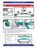
Страница 17: ...blade removal is easy Simply start by removing the four retaining pins Fig 52 turn the floor tool over and separate the blade carrier from the body Fig 53 54 Peel away the blades from their locating l...

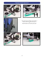
Страница 18: ...18 If your machine leaves streaks on the cleaned floor either clean the floor tool blade See page 13 or adjust blade pressure for optimum performance Floor tool Height Adjustment...

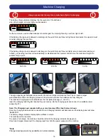
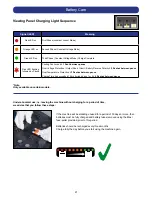
Страница 19: ...play panel will show INHIBITED The battery charge indicator display lights will flash in unison The machine will not operate To ensure a full charge the machine should be left until the charging indic...

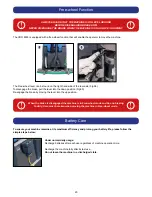
Страница 20: ...e in Free wheel mode The Free wheel lever can be found on the right hand side of the rear axle Fig 58 To disengage the brake pull the lever into the down position Fig 59 Re engage the brake by moving...

Страница 21: ...n pause Charge Time has exceeded 10 hrs during phase 1 or 2 4 flashes between pause Under abnormal use i e leaving the machine without charging for a period of time we advise that you follow these ste...

Страница 22: ...short circuit to a battery Motor will not operate Check all connections and leads between the motor and controller 4 Flashes with pause Battery Lockout The battery charge level has fallen below the b...

Страница 23: ...hange type of brush Restart machine UNDER VOLTS Battery voltage dropped below 21 Volts Left most battery LED flashes Batteries require recharging Faulty cell on battery Machine will not operate Batter...

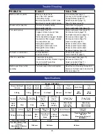
Страница 24: ...le or no water flow Clean water tank empty Clean water tank filter blocked clogged Incorrect water flow setting Brush deck raised Fill clean water tank page 10 Remove and clean 16 Adjust as desired Pa...

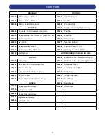
Страница 25: ...013 Squeegee Lift Inner Cable Kit 221079 Chargling Lead V34 EURO 208156 M6 Pinch Bolt BOTTOM TANK STEERING COLUMN FILTERS 237685 Bottom Tank Scuff Moulding Left Hand 230278 Water Pump 237684 Bottom Ta...

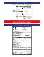
Страница 26: ...2006 EN61000 3 3 1995 A1 A2 BS EN 62233 2008 A technical construction file for this equipment is retained at the manufacturer s address under the authorisation of the following signatory Signed Date...

Страница 27: ...27...
Страница 28: ...o uk Specification subject to change without prior notice www numatic co uk Numatic International Limited This machine has been packed with the following Charging Lead Fuses Keys Signed Distributed by...

Отзывы: