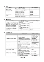
background image

Page 

42

 / 

48


Possible Cause 

Corrective Action 

The implement is not fit for the 
bulldozer. 

Choose the proper 
implement. 


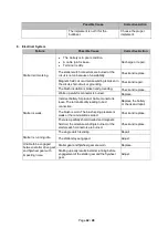
6.  Electrical System 

Failure 

Possible Cause 

Corrective Action 

Starter 

isn’t working. 

  The  battery is in poor condition.   


A cable joint is loose. 

  Terminal is dirty. 

Recharge or repair. 

The starter switch connectors are burned or the 
circuit is not on because of unsuitability. 

Check and replace. 

Magnetic field coil or armature winding is broken in 
the circuit, short-circuit, or grounding. 

Check and repair. 

The brush insulation is broken and grounding. 

Check and replace. 

Warm-

up switch’s connector is burned. 

Replace. 

Starter is  weak. 

Incorrect battery for product. Cable connector is 
loose. 

The terminal’s dirty leading to bad 

connection. 

Replace the battery,  
or check and repair. 

The brush is worn. The brush spring pressure is 
weak or the commutator is soiled. 

Check and replace. 

There is a partially short-circuited and magnetic 
field coil, the armature winding is burned, or the 
starter switch connectors are burned. 

Check and replace. 

Starter  is running idle. 

The single clutch is sliding. 

Repair. 

The starter stays engaged. 

Adjust. 

Unable to be engaged 
between starter drive gear 
and flywheel gear with 
impacting noise. 

Starter gear and flywheel gear are worn. 

Replace. 

Starting up early results in starter running before 
engagement of the starter gear and the flywheel 
gear. 

Adjust. 

Содержание 40XTD

Страница 1: ...Manual WARNING Read carefully and understand all ASSEMBLY AND OPERATION INSTRUCTIONS before operating Failure to follow the safety rules and other basic safety precautions may result in serious perso...

Страница 2: ...that you read the entire manual to become familiar with this product before you begin using it This bulldozer is designed for certain applications only Northern Tool and Equipment is not responsible f...

Страница 3: ...cations 4 Important Safety Information 6 Specific Operation Warnings 8 Grounding 10 Safety and Product Labels 10 Before Each Use 14 Operating Instructions 16 After Each Use 33 Maintenance 33 Troublesh...

Страница 4: ...be used with implements such as a backhoe post hole digger cultivator and more Includes a heavy duty seat and easy to use controls Packaging Contents 40XTD Bulldozer Bulldozer Owner s Manual Bulldozer...

Страница 5: ...n device Helical spring adjusted by screw Number of shoes 39 1pitch 109mm Hydraulic Blade and 3 point Hitch System Gear pump Spline Clockwise 26 32DP Rated capacity 29 4 LPM 7 7 GPM depending on rotat...

Страница 6: ...oped a thorough understanding of how it works Do not modify this product in any way Unauthorized modification may impair the function and or safety and could affect the life of the product There are s...

Страница 7: ...ention while operating the tool may result in serious personal injury Dress properly Do not wear loose clothing dangling objects or jewelry Keep your hair clothing and gloves away from moving parts Lo...

Страница 8: ...rate the product without the guards in place Do not leave the tool running unattended Specific Operation Warnings WARNING To prevent serious injury or property damage read and understand owner s manua...

Страница 9: ...hout all driveline tractor and equipment shields in place Do not operate without driveline securely attached at both ends Do not operate without driveline shields that turn freely on driveline CRUSH A...

Страница 10: ...he grounding instructions or if you are not sure the tool is properly grounded Grounded Tools Tools with 3 Prong Plugs The coolant is equipped with a heater which has a 3 prong plug This needs to be g...

Страница 11: ...ure Operational Warnings Prop 65 Warning Decals 1 19 Electrocution Hazard Danger Decal Fall Hazard Warning Decals Engine Notice Decal 1 20 Diesel Fuel Decal 1 21 Diesel Fuel Drain Decal 1 22 Parking B...

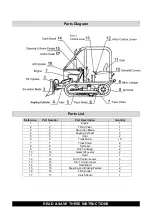
Страница 12: ...Page 12 48 7 8 9 10 11 12 13 14 15 16 17...

Страница 13: ...Page 13 48 18 19 20 21 22 23 24 25...

Страница 14: ...tup check all fluids including engine oil hydraulic oil and coolant Before each use inspect track tension and adjust if needed Keep all bystanders at least 20 feet away from work area To avoid propert...

Страница 15: ...ss it before continuing the run in process 48 hour Run in Under Load Conditions Run in with load means that it s necessary to run the dozer with different loads The load should be increased gradually...

Страница 16: ...draulic system regularly for leaks Hydraulic fluid escaping through even a pin size hole opening can puncture skin and cause blood poisoning Wear proper hand and eye protection when searching for leak...

Страница 17: ...ic lines Check with utility company for underground utilities before excavating FALL HAZARD On entry and exit of the dozer Maintain 3 points of contact at all times Climb up forwards exit backwards Ne...

Страница 18: ...ockwise to ON all circuits except warm up and start up circuit are on after start up the key is kept in this position Throttle Control Turn clockwise to increase throttle 10 grades for accelerating ad...

Страница 19: ...dle forward to increase speed Push the handle backward to decrease speed Put the handle in neutral so the PTO is not engaged The clutch pedal must be pushed all the way in before using the handle Driv...

Страница 20: ...heck the oil lever before starting engine Pull out the transmission fluid dipstick and check the transmission fluid at the floorboard before starting the engine While it s cold open the filler cap on...

Страница 21: ...ty damage do not leave key in H position for more than 15 seconds Keep the engine at idle speed of about 600r min for several minutes after start up In cold weather in order to ensure the engine is ea...

Страница 22: ...cold Direct Start up Direct start up can be done when the environment temperature is above 41 F 5 C or the engine is hot 1 Press the clutch pedal completely in and turn the choke control to the ST pos...

Страница 23: ...keep bystanders out of the area 2 When the engine is running at low speed push the clutch pedal in completely and then put the main gearshift and auxiliary gearshift into the position see Fig 2 3 Slow...

Страница 24: ...his is very dangerous and the bulldozer can roll over Selecting Proper Gearshift Notice When shifting gears the clutch has to be completely disengaged during operation 1 The highest productivity and m...

Страница 25: ...temperature is less than 0 C and antifreeze is not used slowly decrease the coolant s temperature to 122 F 131 F 50 55 C when the bulldozer is running and then turn on the draining plug tap Cover the...

Страница 26: ...trol handle has been put in the neutral position and the cover of the shaft are taken off connect the implement to the bulldozer as directed in the instructions Push in the clutch pedal completely to...

Страница 27: ...of the chassis To check and adjust the engine refer to the 403F E17T Perkins Operation and Maintenance Manual Notice The gearbox main drive and final drive of a new bulldozer have been adjusted by th...

Страница 28: ...the free stroke disappear and clutch clip When this occurs it s necessary to check and adjust the control system Fig 3 Fig 3 Turn the adjusting fork to shorten or extend the push rod to adjust the fr...

Страница 29: ...ning when there is no oil in the gearbox case The backlash between two spiral bevel gears should be 0 15 0 25mm The ideal imprint is shown in Fig 7 and Table 1 The imprint of the spiral bevel gears pi...

Страница 30: ...a light load the length of the imprint should be about half of the total length of the gear tooth While shifting to the larger end of the gears with a full load the imprint of the gears should approa...

Страница 31: ...bevel gear shaft should be 0 7 1 0Nm Final Drive 1 Tighten the outer cover of the final drive case with six bolts The rated torque should be 30 35Nm 2 Tighten the inner cover of the final drive case w...

Страница 32: ...of the groove as shown in Fig 7 f Lastly tighten all nuts on the steering adjusting rods steering pull rod and brake pull rod Notice Tighten the brake and steering pedal completely The steering clutc...

Страница 33: ...the ground 4 Disengage the PTO 5 Do not leave the machine until the engine and all parts have stopped Maintenance WARNING Always wear the proper protective equipment including ANSI Z87 1 compliant eye...

Страница 34: ...on If the sag exceeds 2 5mm adjust i Inspect the outer connections and tighten any loose connections Check the joints fittings and tubes for any leakage If found repair or replace Verify that the engi...

Страница 35: ...tors Clean the injector If necessary adjust or replace it Check the clearances of the inlet and the exhaust valves The normal clearance of the inlet valve is 0 35mm and the normal clearance of the exh...

Страница 36: ...rboard Remove the dipstick and check the oil level It should not exceed the maximum level Step 1 Screw off the four bolts on the magnetic cover and release the gear oil Step 2 Clean up the cover and a...

Страница 37: ...h and empty the oil from the final drive case Step 2 Put the sealing washer on the plug and then insert the plug Step 3 Screw off the plug tap and fill the oil into tank Step 4 Open the plug and check...

Страница 38: ...ease Swing shaft sleeves Water pump bearings Clutch release bearing Cylinder pins Winter Maintenance Use lubricant grease and fuel appropriate for winter Antifreeze is recommended Drain out all the wa...

Страница 39: ...dozer does not move There is some grease or oil on the disc surface Replace and repair the leaking parts Free stroke is too small or doesn t exist Re adjust Driven disc is curled or unevenly worn Rep...

Страница 40: ...ar Gear shift is difficult or impossible Clutch will not completely disengage Inspect and repair if necessary The rounding of the gear end is worn or broken Replace the gear The fitting between the sl...

Страница 41: ...brake is too small Re adjust 5 Hydraulic System Possible Cause Corrective Action Load will not lift or lifts slowly There s much air in the system Check the system for leakage and repair The filter i...

Страница 42: ...tch s connector is burned Replace Starter is weak Incorrect battery for product Cable connector is loose The terminal s dirty leading to bad connection Replace the battery or check and repair The brus...

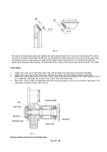
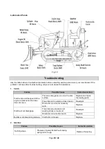
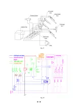
Страница 43: ...43 48 Fig 11 Fig 12...

Страница 44: ...der 1 3 3 Six action Blade 1 4 4 Angling Cylinder 2 5 5 Idler 2 6 6 Track Roller 10 7 7 Track Chain 2 8 8 Sprocket 2 9 9 Hitch Linkage 2 10 10 Gearshift Levers 2 11 11 Seat 1 12 12 Hitch Control Lever...

Страница 45: ...s provided are a convenient reference to the location and position of parts in the assembly sequence When ordering parts the following information will be required item description item model number i...

Страница 46: ...ng their regular business hours All transportation costs after the first 60 days of ownership are the responsibility of the equipment owner Exclusions and Warranty Disclaimers This limited warranty ap...

Страница 47: ...Page 47 of 48 Distributed by Northern Tool Equipment Company Inc Burnsville Minnesota 55306 www northerntool com Made in China...

Отзывы: