


Maintenance, continued
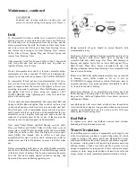
J-1455 MOTOR
Exploded view showing method of jacking rear end
plate out of motor housing for changing rotor blades
Drill
To disassemble, first move shifter level to neutral, hold down
feed nut stop pin, reverse motor and run screw out of feed nut.
The drill may now be disconnected from the air line and the
motor removed from the drill. Next remove Drive Gear Screw
and remove drive shaft drive gear from Rear Housing Cover,
and remove rear housing cover from Housing. Next, remove
Shifter Sleeve Detent Spring Plug and Detent Spring and
remove Front Housing Cover.
After removing Castle Nut from end of Drive Shaft, drive shaft
with feed gears and feed nut assembly may be pulled out
together. Remove Drive Sleeve.
Do not disassemble drive shaft or feed nut assembly unless
replacement of parts is required. If feed nut is disassembled,
remove Lock Nuts with two spanners, LEFT HAND THREAD!
To reassemble, if feed nut has been disassembled, first drive
Key into slot in nut and place feed gears on feed nut with the
gears in sequence from the lowest to the highest or the reverse,
according to operator’s preference. Place Ball Bearing on gears
and tighten Lock Nuts in place, using two spanners. LEFT
HAND THREAD! After tightening nuts, stake in at least four
places with center punch.
If drive shaft has been disassembled, first place Steel Ball and
Spring in Shifter Rod and tighten Plug in end of rod. Insert rod
in drive shaft and drive Feed Gear Key into rod under steel ball.
Pack feed gears with recommended grease and place on drive
shaft to mate with those on the feed nut. Remember that the two
assemblies are put together from opposite ends and that the
sequence of assembly must be the reverse of that used on the
feed nut in order to pair feed gears on final assembly.
Next, place Thrust Washer and Ball Bearing on drive shaft.
Place one Washer and Shifter Collar in Shifter Sleeve, invert
sleeve, place second Washer on shifter collar and screw Shifter
Collar Nut on shifter collar. Place Pin Retainer on drive shaft,
insert Shifter Pin through hole in shifter rod and place
assembled shifter sleeve on drive shaft, entering pin in slot in
shifter collar nut. Place Pin Retainer in groove in shifter collar
nut.
Before reassembling drill, remove the shifter handle assembly
and the drive Shaft Front Bearing. If two Ball Bearings located
in the drive sleeve chamber of the housing require replacement,
drive the first down tightly against should in housing, add
Spacer and drive second bearing against spacer.
During assembly all parts should be coated liberally with
recommended grease.
Mesh gears of drive shaft and feed nut assemblies and insert in
housing together. Hold Drive Shaft Gear in housing and
assemble with drive shaft using Key. Place Ball Bearing in
housing and tighten Castle Nut on drive shaft against Drive
Shaft Washer. Place Drive Sleeve assembled with one Call
Bearing in housing. Fasten Front Housing Cover assembled with
Grease Seal on housing.
Rotate drive shaft until shifter handle assembly may be inserted
in housing, rotate shifter handle as far as it will go
CLOCKWISE to engage shifter key with last feed gear, remove
assembly and place in its proper position, with handle to left of
‘N’ toward chuck end of housing.
Fasten Rear Housing Cover assembled with Grease Seal and
Roller Bearing to housing, place drive shaft drive gear and two
Keys on drive shaft and tighten Drive Gear Screw into drive
shaft against Washer.
Assemble motor with swivel head, attach air line, thread drive
screw into feed nut, depress stop pin and, with motor on forward
rotation, open throttle and run screw into nut. DO NOT jam
chuck against front housing cover.
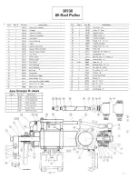
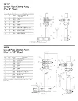
Rod Puller
To replace worn piston cup leathers, unscrew back cylinder
head and pull out piston and piston rod.
Water Circulation
Good drilling practice requires a dependable water supply used
at the lowest pressure conducive to good sludge removal, which
results in saving of the pump, power and diamond bits. Local
conditions will dictate the correct pressure and volume required,
for instance, sticky ground will require high pressure and deep
drilling, because of leaky rod joints and the necessity to keep
sludge in suspension for long periods of time will require larger
volumes of water. Large holes drilled with small rods will need
a large volume of water to maintain normal circulation velocity.