Operation
For efficient operation of the CP65 Diamond Core and Blast
Hole Drill, at least 80 psi OPERATING pressure should be
maintained at the drill. Use 1-1/4 in. hose up to 25 feet and 1-
1/2 in. hose for longer lengths.
Blow our air hose before attaching to inlet. Remove and clean
air screen at frequent intervals, being careful not to damage or
distort screen and allow grit or scale to get into motor.
If the motor freezes from excess moisture in the air line, remove
hose from the drill and blow out hose until the line is clear. If
this does not remove water, the use of an air receiver is
recommended. After blowing out line, inspect and clean air
screen, since quantities of water moving through the line
generally carry scale and grit which may plug screen and
seriously impede air flow.
CAUTION: Do not over speed motor on light loads.
This may cause the blades to burn and delaminate.
Gear Changes
There are four feed gear changes on the CP65, the rating figure
representing the number of revolutions of the bit per inch of
advance. The Specification Table lists feeds available, the drill
being supplied with 100, 200, 300 and 500 feed gears unles
otherwise specified.
The drill is assembled with fast feeds toward the front and
slower feeds toward the rear. These may be reversed at
operator’s discretion, since it makes no difference in actual
operation. Gears are engaged by turning the shifter handle until
the longer part of the handle is midway between the letters “N”
stamped on the housing or as far as it will go in either direction.
As assembled, turn the shifter handle CLOCKWISE for a fast
feed or COUNTER-CLOCKWISE for a slow feed. Three
neutral positions, one between each feed, are marked by the
letter “N” on the housing. To return feed screw when run out,
close throttle, move shifter lever to NEUTRAL position, hold
down feed nut stop pin and open throttle slowly. When chuck or
coupling is about one inch from front of housing cover, release
stop pin and close throttle. To re-engage gears, move shifter
handle toward gear to be used, open throttle slightly and the
feed gear key should slip into position. If the gear key does not
immediately slip into slot in gear, do not attempt to force it, but
hold shifter handle against gear until correct position is reached
and key slips into place.
CAUTION: Be careful not to jam chuck against front
housing when returning the feed screw.
If jamming occurs, CLOSE THROTTLE VALVE, leave shifter
handle in NEUTRAL position, hold down feed nut stop pin and
turn chuck or feed screw backward to loosen it.
With shifter handle in neutral, feed screw may be returned
rapidly (taking care not to jam chuck against housing) or may be
run forward into position just as rapidly by
reversing motor. If
desired, the screw may be run completely out of the feed nut.
Feed screw may be run normally a full 24” without difficulty.
A full 26” run is obtained without running feed screw down into
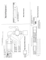
feed nut by using the Blasthole Feed Screw and EW Blasthole
Coupling with High Speed Water Swivel attached directly to the
feed screw.
Speeds
As normally assembled, unless another speed range has been
specified, the motor pinion and drive gear set for the CP65 gives
a nominal spindle speed of 1500 RPM with a gear reduction of
two to one. This gives the drill enough torque for holes up to
600 feet deep and plenty of speed for coring.
Other gear combinations are available for the most difficult
conditions, such as deeper NX holes where the 1000 RPM gear
set will give extremely high torque, or for blasthole drilling
where the 3000 RPM set will give a high rotating speed for
drilling up to 24 in. a minute.
Speed of rotation is not to be confused with feed, which is a
definite ratio of revolutions per inch of feed screw advance. For
example, when drilling in the 200 feed gear, the feed screw will
be advancing one inch for every 200 revolutions of the screw.
High rotational speeds will drill faster, but the ratio of
revolutions of the screw to each inch the screw advances
remains constant.
Maintenance
Motor
The motor consists of a cylinder in which a rotor is mounted
eccentrically, six slots in the rotor hold six laminated, phenolic
blades which move in and out against the cylinder wall as the
rotor revolves. These blades and the rotor are the only rotating
parts. Ball bearings, end plates, rotor housing liner and blades
are the only wearing parts. It is recommended that an extra set
be kept on hand. Adequate lubrication is important in
maintaining rotor blades, as running a relatively short time
without lubrication will cause them to wear rapidly and
unevenly, burn or delaminate.
The rotor blades may be removed and the wearing faces dressed
down with sandpaper or a file in case of uneven wear. Care must
be taken to keep the wearing faces square with the sides.
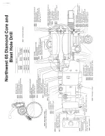
To remove or change blades, remove eight Cap Screws holding
the Rotor Housing Cover to the Rotor Housing and remove
cover. Remove the Rotor Locking Nut and, with two Allen
wrenches tighten the Set Screws to jack the End Plate out of the
housing. The rotor blades may then be removed for inspection
or replacement. Before replacing end plate, retract Set Screws to
avoid interference during assembly.
To remove the Rotor Housing Liner or
to change Ball Bearings,
the motor must be removed from drill and, after the Rotor
Housing Cover has been removed, the assembly of rotor, liner
and end plates may be pushed out the rear end of the motor
housing for inspection or replacement.


