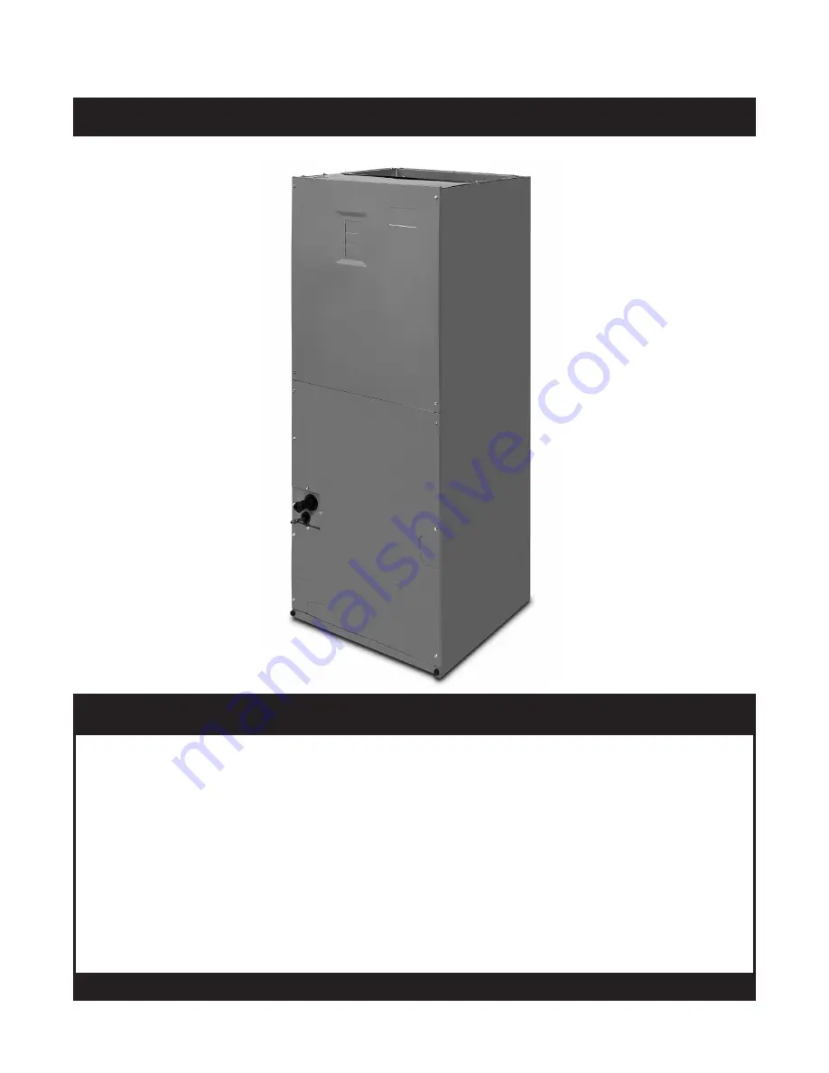
background image

AIR HANDLER

B64BM SERIES

INSTALLATION INSTRUCTIONS

IMPORTANT

ATTENTION INSTALLERS:

It is your responsibility to know this product better than your customer. This includes being 
able to install the product according to strict safety guidelines and instructing the customer on 
how to operate and maintain the equipment for the life of the product. Safety should always be 
the deciding factor when installing this product and using common sense plays an important 
role as well. Pay attention to all safety warnings and any other special notes highlighted in the 
manual. Improper installation of the furnace or failure to follow safety warnings could result in 
serious injury, death, or property damage.
These instructions are primarily intended to assist qualified individuals experienced in the proper 
installation of this appliance. Some local codes require licensed installation/service personnel 
for this type of equipment. Please read all instructions carefully before starting the installation. 
Return these instructions to the customer’s package for future reference.

DO NOT DESTROY. PLEASE READ CAREFULLY & KEEP IN A SAFE PLACE FOR FUTURE REFERENCE.

Содержание B64BM Series

Страница 1: ...as well Pay attention to all safety warnings and any other special notes highlighted in the manual Improper installation of the furnace or failure to follow safety warnings could result in serious inj...

Страница 2: ...10 Control Board 10 Twinning 10 Line Low Voltage Connections 11 Heater Kits 11 Electronic Air Cleaner EAC 11 STARTUP ADJUSTMENTS 11 Before You Start the Unit 11 Air Circulation 11 Running the Blower C...

Страница 3: ...s manual during the installation service and operation of this unit Unqualified individuals should not attempt to interpret these instructions or install this equipment Failure to follow safety recomm...

Страница 4: ...ent Refer to applicable building codes for details Static pressure drop through louvered openings and through return air plenums should be considered in the overallductdesigninthedeterminationofthetot...

Страница 5: ...ance be sure to install all the needed gaskets and grommets around penetrations into the air handler such as for electrical wiring AIR HANDLER INSTALLATION B64 series air handlers are shipped ready fo...

Страница 6: ...Right Installations 1 Remove the coil access door Unscrew the line set tube close off plate from the front left cabinet rail 2 Slide the coil and drain pan assembly out of the unit 3 Remove the sheet...

Страница 7: ...ult in equipment damage personal injury or death The installer should make every effort to ensure the field installed refrigerant containing components of the system have been installed in accordance...

Страница 8: ...htenanadditional1 4turnusingtwowrenches The movement of the two lines will show how much the nut is tightened If a torque wrench is used tighten to 10 12 ft lbs or 14 16 Nm Connecting the Linesets The...

Страница 9: ...d tubing or pvc pipe and adequately trapped Both drain tubes must have a minimum diameter of 3 4 and be trapped separately IMPORTANT Failure to install a trap may result in condensation overflowing th...

Страница 10: ...plate Use UL listed conduit and conduit connectors for connecting the supply wires to the unit and for proper grounding Field supplied bushings for the power supply cables must be added to support and...

Страница 11: ...on is sized properly Verify filter is properly and securely installed IMPORTANT Before starting the unit install the initial charge on units that are factory shipped with a nitrogen holding charge 1 R...

Страница 12: ...locations are shown in Figure 11 page 15 If any component of the air handler must be replaced use only factory authorized replacement parts specified in the Replacement Parts List provided online WAR...

Страница 13: ...caution when preparing coils for field connections If repairs makeitnecessaryforevacuationandcharging it should only be attempted by qualified trained personnel thoroughly familiar with this equipmen...

Страница 14: ...11 4 15 8 17 8 11 4 3 1 4 2 5 8 11 8 K O typ 13 4 K O typ 1 7 8 3 5 8 5 5 8 DETAIL D 3 1 4 2 1 4 15 1 4 13 SUCTION LIQUID W 1 1 8 1 7 8 7 8 K O H 22 A CABINET SIZE H W A DETAIL D A 43 5 16 14 3 16 12...

Страница 15: ...Mount Kit Blower Motor Transformer Capacitor Circuit Breaker 60A Heating Element Assembly Filter Tracks Blower Wheel Blower Housing Motor Control Board Filter Door Upper Door Assembly Lower Door Assem...

Страница 16: ...s for maximum recommended external static pressure Table 4 B64BM Airflow Data With Horizontal Drain Pan DRY COIL ESP 0 1 0 2 0 3 0 4 0 5 0 6 0 7 0 8 18K A CABINET Low 760 722 676 622 561 492 414 330 M...

Страница 17: ...tly Blower off after 15 second delay W1 Y AUX HEAT ON 5 KW Stage 1 Heat on instantly Cool blower on after 3 second delay 10 KW Stage 1 Heat on instantly Cool blower on after 3 second delay 15 KW Stage...

Страница 18: ...R C E O Y Thermostat Typical Heat Pump with Standard Air Handler Heat Pump NOTE Jumper between W2 E is required when no OD T Stat is used W1 Y G R C Air Handler W1 Y G R C R C Y W2 O W2 NOTE See step...

Страница 19: ...19 LED 1 BLWDTC BLWDTC_R HEAT COOL EAC L 1 L 2 P2 R C G W Y 3A Fuse HEATER P1 Figure 14 Single Stage Control Board...

Страница 20: ...G RELAY RELAY Y L2 L1 EAC COOL HEAT W G R C R C L2 L1 7 6 5 4 3 2 1 1 COM 2 CAP 3 CAP 4 HI 5 MED 6 LOW 240 24 V 208 COM TRANSFORMER R C LOCATION OF T CONNECTOR MOTOR 3 SPEED 4 PIN PLUG 18 BLOWER LIMIT...

Страница 21: ...21...

Страница 22: ...22...

Страница 23: ...23...

Страница 24: ...t according to strict safety guidelines and instructing the customer on how to operate and maintain the equipment for the life of the product Safety should always be the deciding factor when installin...

Отзывы: