© Norsat International Inc.
(“Norsat”) All Rights Reserved
2021-04-23 039092 Rev C
17
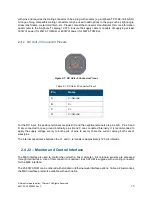
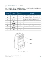
Table 2-3: J2 Pinouts for ATOM Configurations
Connect
or Pin
Standard
Configur
ation
Ethernet
Configura
tion
Signal Description
A
RS-485
Tx-
RS-485
Tx-
Host computer Tx- signal (signal into unit)
B
RS-485
Tx+
RS-485
Tx+
Host computer Tx+ signal (signal into unit)
C
RS-485
Rx+
RS-485
Rx+
Host computer Rx+ signal (signal out of unit)
D
Mute
Mute
Controls Muting of Amplifier
E
Eth Rx+
Ethernet host computer Rx+ signal (signal out of unit)
RS-232
Rx
RS-232 host computer Rx signal (signal out of unit)
F
Eth Tx+
Ethernet host computer Tx+ signal (signal into unit)
RS-232
Tx
RS-232 host computer Tx signal (signal into of unit)
G
GND
GND
Ground reference for Ethernet/RS-485/RS-232 signals. This is
internally connected to case ground.
H
Eth Rx-
Ethernet host computer Rx- signal (signal out of unit)
NC
NA
J
RS-485
Rx-
RS-485
Rx-
Host computer Rx- signal (signal out of unit)
K
Eth Tx-
Ethernet host computer Tx- signal (signal into unit)
NC
NA
Ground Pin(s): Pin G
Ground/shield for Ethernet, RS-485, RS-232 & Mute signals. This is internally connected to the case
ground. Do not exceed 100mA.
Mute Control: Pin D
This pin controls the hardware mute state of the ATOM. When muted, the power transistors are turned off,
reducing power consumption and providing an RF output noise close to the thermal noise floor.
The operation of this pin is fully configurable through the M&C Interface. Pin D can be biased with either
an internal Pull-Down (to 0V) or an internal Pull-Up (to 4V). Pin D is also configurable to be either active
high (3-5V on Pin D will mute the unit) or active low (0-0.8V on Pin D will mute the unit). All voltages are
relative to Pin G or the Case Ground.
Because of the configurable pull-down / pull-up resistor, the unit can be configured to be active (i.e. not
muted) when Pin D is left floating. Therefore, it is possible to operate the unit with no connection pin D.


