© Norsat International Inc.
(“Norsat”) All Rights Reserved
2021-04-23 039092 Rev C
19
Ethernet Interface: Pins E, F, H, & K
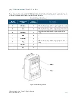
These four pins form a standard 10/100Mbps Ethernet link. Table 2-5 and Figure 2-9 summarize how to
construct an Ethernet M&C cable to access the web interface.
Table 2-5: Ethernet Cable Pinout
ATOM
Connector
Twisted Pair
Cable
RJ-45
Connector
Description
F
Wht/Grn
1
Ethernet host computer Tx+ signal (signal into unit)
K
Grn
2
Ethernet host computer Tx- signal (signal into unit)
E
Wht/Org
3
Ethernet host computer Rx+ signal (signal out of
unit)
-
Blu
4
-
-
Wht/Blu
5
-
H
Org
6
Ethernet host computer Rx- signal (signal out of
unit)
-
Wht/Brn
7
-
-
Brn
8
-
Figure 2-9: RJ-45 Plug Pinout


