BU 0750 GB
Technical design subject to change
97
Parameter
Setting value / Description / Note
Parameter
set
Available with option
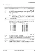
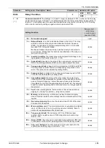
P412
Nom.val process ctrl
P
Always available
0.0 ... 10.0 V
[ 5.0 ]
To feed a setpoint to the process controller which is to be valid for a prolonged period and will hardly
ever be changed.
Only with P400 = 14 ... 16 (process controller). For more detailed information see Section 10.2.
P413
PID control P comp.
P
Always available
0 ... 400.0 %
[ 10.0 ]
For this parameter to be effective, the PID actual frequency function must have been selected.
In the event of a controlling error, the P component of the PID controller will determine the extent of
the frequency jump in relation to the control offset.
Ex.: If P413 has been set at 10%, and if the controlling error amounts to 50%, 5% is added to the
current setpoint.
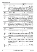
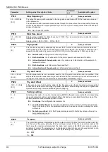
P414
PID control I comp.
P
Always available
0 ... 300.0 %/ms
[ 1.0 ]
For this parameter to be effective, the
PID actual frequency function
must have been selected.
In the event of a controlling error, the I component of the PID controller will determine the change of
the frequency in relation to time.
P415
PID control D comp.
P
Always available
0 ... 400.0 %ms
[ 1.0 ]
For this parameter to be effective, the
PID actual frequency function
must have been selected.
In the event of a controlling error, the D component of the PID controller will determine the change of
the frequency multiplied by time (%ms).
If any of the analogue inputs has been assigned the
function process controller actual
value
, that parameter will determine the controller limitation (%) downstream of PI control-
ler. For more detailed information see Section 10.2.
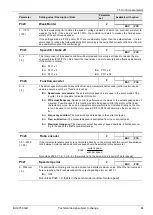
P416
Ramptime PI setpoint
P
Always available
0 ... 99.99s
[ 2.00 ]
For this parameter to be effective, the
PID actual frequency function
must have been selected.
Ramp for the PID setpoint
Note:
For more details about the PID and Process controller see chap. 10.2 and 10.3
P417
Offset analog outp. 1
P
STD
MLT
-10.0 ... +10.0 V
[ 0.0 ]
When the analogue output function is used, this parameter allows for an offset to be defined which
will facilitate processing of the analogue signal in other devices.
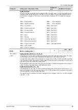
If a digital function is assigned to the analogue output, the difference between operate point and re-
lease point (hysteresis) can be set in the present parameter.


