


NORDAC SK 750E manual
36
Technical design subject to change
BU 0750 GB
3.2.7 InterBus module
(SK TU2-IBS, part no.: 275130080)
(SK TU2-IBS-C, part no.: 275170080)
With the InterBus system data can be exchanged among a major
number of automation devices whatever their description. In fact
stored-program controllers, PC's, operating and monitoring units can
all be connected to a single bus up to a total number of 256 and com-
municate with one another in serial bit mode.
When connected into a bus circuit, NORDAC frequency inverters will
allow for remote control. Data width is variable (3 words; 5 words), the
baud rate amounts to 500kbps (2Mbps as an option). There is no need
to provide a terminating resistor as it is already integrated. Devices
connected into the circuit are addressed automatically depending on
their physical location within the system
.
To preserve the continuity of bus operation, an external 24-volt supply
will be required.
NOTE:
For more detailed information please refer to the
BU 0070
Operating Instructions or contact the
supplier of the inverter.
3.2.8 AS Interface
(SK TU2-AS1, part no.: 275130120)
(SK TU2-AS1-C, part no.: 275170120)
The
A
ctor-
S
ensor
I
nterface (AS Interface) is a bus system for the simple
field bus level. The transmission principle is a single-master system involv-
ing cyclic polling. ASI allows for 31 slaves max. (or 62 A/B slaves respec-
tively) to be operated via an unshielded two-wire cable with a maximum
length of 100m, the network structure (tree / linear / star) being as pre-
ferred. The AS interface line (yellow) is for transmitting data and electric
power. A second two-wire cable (black) can be provided to supply an auxil-
iary low voltage (24V). The bus units are addressed by the master device
which ensures other management functions as well, or by an extra ad-
dressing device. The 4 bits of useful data (per direction of transmission)
are transmitted in cyclic mode, the cycle time being 5ms max. An effective
error protection is ensured. Some slave profiles (e.g. Slave Profile 7.4) additionally allow for transmission of
larger amounts of data. The bus system is defined in the
AS-Interface Complete Specification
.
NOTE:
For more detailed information please refer to the
BU 0090
Operating Instructions or contact the
supplier of the frequency inverter.
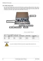
Subassembly status LEDs
ST (red/green)
Subassembly error/ready
InterBus status LEDs
UL (green)
Supply voltage being applied
RC (green)
Remote Check, remote bus to preceding InterBus device is o.k.
BA (green)
Bus active, InterBus data being exchanged (bus running)
RD (yellow)
Remote bus disabled, remote bus to the next InterBus device is
disabled.
TR (green)
Transmit, data are being transmitted from/to a connected device
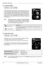
Status LEDs
Device S/E
(red/green)
Status/error of the subassembly
AS- Int. PWR/FLT
(red/green)
Standard status display for AS-Interface slaves.


