


BU 0750 GB
Technical design subject to change
21
2.9.1 Mains connection (PE, L1, L2, L3)
There is no need for special protection on the inverter mains input, but standard
line protection (cf. Section 9, Technical data) and a master switch/master contac-
tor are recommended anyhow.
Note:
For this frequency inverter type to be connected to an
IT-net
only slight
modification will be required. Please consult your supplier.
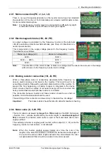
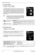
2.9.2 Electromagnetic brake (+Br, -Br, PE)
An output voltage is generated by the frequency inverter at the terminals
+Br/-Br to actuate an electromechanical brake (see Chap. 2.9 Electrical con-
nection power section).
This is dependent on the supply voltage present in the frequency inverter.
The allocation is as follows:
Mains input voltage (AC)
Brake coil voltage (DC)
400V ~
180V =
460V ~ ... 480V ~
205V =
230V ~
105V =
Note:
The allocation of the correct brake or brake coil voltage must be taken into account in the design
with reference to the frequency inverter mains voltage.
2.9.3 Braking resistor connection (+B, -B, PE)
When a three-phase motor is dynamically decelerated (the frequency re-
duced), electric energy is fed back to the inverter. This could result in an
overvoltage situation, followed by automatic disconnection of the inverter. To
prevent this from happening, a braking chopper is integrated in the device
which ensures that the surplus of recovered energy will be converted into
heat, provided that an external brake resistor is connected.
The connection between inverter and brake resistor should be as short as
possible, and a shielded cable should be used.
The switching of this connection is allowed only in the state free of voltage!
Important:
The brake resistor should be rated to allow for maximum heating.
2.9.4 Motor cable (U, V, W, PE)
The motor cable must
never
be
longer
than
150m in all
(as the EMC limit values
– Section 10.4 – will also be affected by the cable length). A
maximum length of
50m
is allowed if a shielded motor cable is used or the metal cable duct is thor-
oughly earthed.
The switching (shooter or engine guard counter) at the output (U, V, W), while the
frequency inverter current delivers, is not allowed!
Note:
When the inverter controls several motors at a time, the sum of the
lengths of the individual cables is considered to be the total cable length. If
the sum of the various cable lengths exceeds the value allowed, the inter-
nal optional motor filter should be included in the order as well.


