7.9 Information
BU 0750 GB
Technical design subject to change
123
Parameter
Setting value / Description / Note
Parameter
set
Available with option
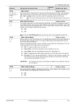
P741
... - 01
...
... - 06
PZD bus out 1...6
Always available
0 ... FFFF hex
This parameter provides information on the status
word currently being used and on the actual values
being transmitted via the bus systems
... - 01
= status word
... - 02
= actual value 1 (P543)
... - 03
= actual value 1 high byte
... - 04
= actual value 2 (P544)
... - 05
= actual value 3 (P545)
... - 06
= Bus-Out bit (P543-P545)
P742
Data base version
Always available
0 ... 9999
Display of the version of the internal database stored in the inverter.
P743
Inverter ID
Always available
0.00 ... 250.00
Display of the inverter output by wattage, such as "
15
" FI rating is 15 kW.
P744
Configuration
Always available
0 ... 9999
This parameter displays the optional subassemblies the FI is able to identify.
The ParameterBox will display this information in clear text.
The ControlBox will display the potential combinations in a coded form. The custom interface
being used is shown on the right. When the code includes the number 1 as the second digit,
this means that an encoder module is additionally installed, while the number 2 refers to the
PosiCon
option.
No I/O
XX00
Basic I/O
XX01
Standard I/O
XX02
Multi I/O
XX03
USS I/O
XX04
CAN I/O
XX05
Profibus I/O
XX06
Encoder
01XX
PosiCon
02XX
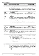
P745
... - 01
... - 02
... - 03
Option Version 1...2
Always available
0 ... 32767
Software version of the subassemblies in-
stalled (not unless they are provided with a
processor of their own).
Array level:
[01] Equipment box/TU
[02] Custom interface
[03] Special extension
P746
... - 01
... - 02
... - 03
Option Status 1...3
Always available
0000 ... FFFF hex
State of subassemblies installed
(when activated)
Array level:
[01] Equipment box/TU
[02] Custom interface
[03] Special extension
P747
Inverter Volt. Range
Always available
1 / 2
Displays the range of supply voltage for which the device in question is suitable ac-
cording to its specification.
1
= 200 … 240V
2
= 380 … 480V
P750
Stat. overcurrent
Always available
0 ... 9999
Number of overcurrent trippings in the course of an operating period
P751
Stat. Overvoltage
Always available
0 ... 9999
Number of overvoltage trippings in the course of an operating period


