START-S5PV
Technical manual
-9-
Description of securities
The control unit dispose of inputs for
CLOSING PHOTO-BEAM
and
STOP
. The first contact is activated only when the
motor is closing or is in pause time; if this safety intervene while the motor is closing, the control unit stops and invert the
motor until a new completely opening, while if the intervention is during the pause time it recharge the pause time and it
doesn’t recluse.
The input
STOP
is activated in any condition. If this input is not connected to the common input (terminal board 16-18) the
control unit won’t accept any control and it stops immediately the motor if it is moving.
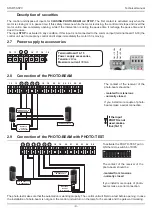
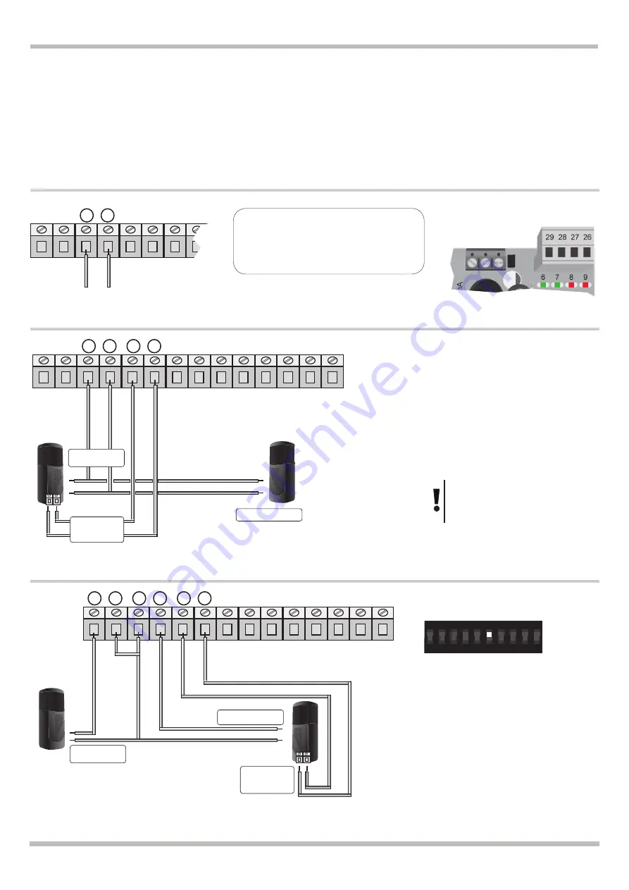
2.8 Connection of the PHOTO-BEAM
12 13 14 15 16 17 18 19 20 21 22 23 24 25
POWER SUPPLY TO
RX PHOTOCELL
Photocell
receiver.
N.C. contact
POWER SUPPLY TO
TX PHOTOCELL
If the input
PHOTO is not
used, make a
link (16-17)
2.9 Connection of the PHOTO-BEAM with PHOTO-TEST
12 13 14 15 16 17 18 19 20 21 22 23 24 25
POWER SUPPLY TO
TX PHOTOCELL
POWER SUPPLY TO
RX PHOTOCELL
Photocell
receiver.
N.C. contact
ON
CTS
2
1
4
3
6
5
8
7
10
9
To activate the PHOTO-TEST put in
ON the micro-switch 6 of DIPA
The contact of the receiver of the
photo-beam should be:
- isolated from tensions
- normally closed
If you install more couple of photo-
beams make a serial connection.
The contact of the receiver of the
photo-beam should be:
- isolated from tensions
- normally closed
If you install more couple of photo-
beams make a serial connection.
The photo-test make sure that the automation is working properly. The control unit will first do a test before opening. In case
the installation of photo-beam is not good, the control unit will turn on the lamp for 5 seconds and the gate won’t working.
2.7 Power supply to accessories
Terminal Board 14-15
Power supply accessories
Tension:
24Vac
Maximum current:
300mA
12 13 14 15 16 17 18 19
Common
Out +24 Vdc
Out +12 Vdc

