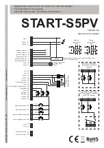
START-S5PV
Technical manual
-7-
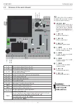
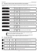
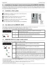
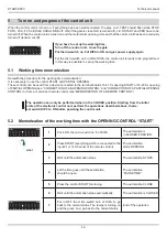
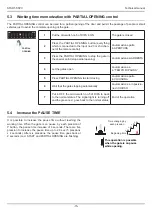
2.2 Scheme of the control board
Out +12 Vdc
Common
Out +24 Vdc
0 V
ac
230 V
ac
400 V
ac
LED
When the control unit is powered,
the lights LED are turned on when
the common contact is closed.
9 - RED - ON
Opening limit switch (NC)
8 - RED - ON
Closing limit switch (NC)
7 - GREEN
it turns on when the OPEN
contact is closed.
6 - GREEN
it turns on when the CLOSE
contact is closed.
4 - GREEN
It turns on when the PEDE-
STRIAN contact is closing.
3 - RED - ON
SERVICES contact closed.
2 - RED - ON
STOP contact closed.
1 - RED - ON
PHOTO contact closed.
5 - GREEN
It turns on when the START
contact is closing.
LED TEST - RED
It indicates if the control uniti s
working properly. It should fl ash
each second and it indicates
that the micro-processor is ac-
tivated and it is waiting for con-
trols.
WARNING!
This control can be
used only with
limit-switches
1
2
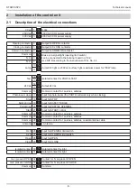
230 Vac power supply of the control unit
1
3
400 Vac power supply of the control unit
4
11
230 Vac power supply of the motor,
230Vac contact for lamps
12
25
Tension for accessories, inputs services and safeties
26
27
Input for closing limit switch
28
29
Input for open and close control
30
31
Free contact for light
32
34
“Man present” function with open and close
DIP A
Set up the function of the control unit
DIP B
Set up the function of the control unit
Pulsante
P
For radio code receiver, power adjustment,
increase of the pause time
Fuses
Fuse for Transformer power supply, Signal Light (term. board 10-11) and
fuse for remote-control switch (term. board 4-5-6):
F1
-
4A
Fuse accessories and logic:
F2
-
630mA
Fuse for brake:
F2
-
630mA
F2 - 630 mA
F1 - 4A
F3 - 630 mA

