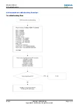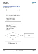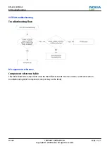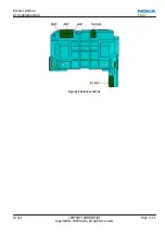
Troubleshooting with RF-shield removed
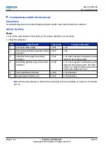
Introduction
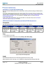
Troubleshooting instructed in the following chapter requires that the RF-shield lid is removed.
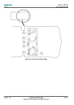
Voltage checking
Steps
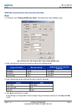
1. Set up the main board in the module jig. The phone should be in local mode.
2. Check the following:
TP#
Signal name
Test point
Voltage (all bands)
1
VCTCXO (G7500) supply
C7501
2.5V
2
RFIC Vapaus (N7500) supply from DC/DC
converter
C7570
2.8V
3
TXFEM (N7520) supply from DC/DC
converter
C7521
1.3V-3.8V (only when transmitting and
depends on output power).
4
WCDMA PA (N7540) supply from DC/DC
converter
C7528
0.7V-3.1V (only when transmitting and
depends on output power). The value
will be 3.1V when settings as described
in the note below are used.
5
Vbat at WCDMA PA (N7540)
C7512
3.7V (Vbattery)
6
Supply input to DC/DC conv
C7527
3.7V (Vbattery)
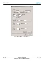
Note:
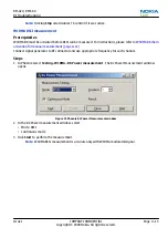
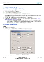
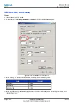
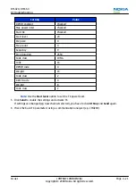
When using settings as shown in the following Tx Control window, the result at TP4 should
be 3.1V.
RM-424; RM-564
RF Troubleshooting
Page 4 –24
COMPANY CONFIDENTIAL
Issue 1
Copyright © 2009 Nokia. All rights reserved.
Содержание 6720 classic
Страница 133: ...4 RF Troubleshooting Nokia Customer Care Issue 1 COMPANY CONFIDENTIAL Page 4 1 Copyright 2009 Nokia All rights reserved ...
Страница 179: ...6 System Module Nokia Customer Care Issue 1 COMPANY CONFIDENTIAL Page 6 1 Copyright 2009 Nokia All rights reserved ...
Страница 209: ...Glossary Nokia Customer Care Issue 1 COMPANY CONFIDENTIAL Page Glossary 1 Copyright 2009 Nokia All rights reserved ...

