background image


TPC6000

6151


User


Manual


25 


Figure


2

11:


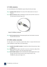
Tighten


the


panel


mounting


clamp


screws.


2.7


Bottom


panel


connectors


The


bottom


panel


connectors


extend


the


capabilities


of


the


panel


PC


but


are


not


essential


for


operation


(except


power)


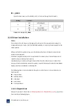
Figure


2

12:


Connectors


2.7.1


LAN


connection


The


RJ

45


connectors


enable


connection


to


an


extend


network.


To


connect


a


LAN


cable


with


a


RJ

45


connector,


please


follow


the


instructions


below.


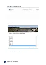
Step


1:


Locate


the


RJ

45


connector


on


the


bottom


panel


of


the


TPC6000

6151.


Step


2:


Align


the


connectors.


Align


the


RJ

45


connector


on


the


LAN


cable


with


one


of


the


RJ

45


connector


on


the


bottom


panel


of


the


TPC6000

6151.


Please


See


Figure


2

13


Содержание TPC6000-6151

Страница 1: ...TPC6000 6151 User Manual 1 User Manual Ver1 4 TPC6000 6151 Industrial Panel PC...

Страница 2: ...gistered trademarks of their respective owners AMI is a trademark of American Megatrends Inc Intel Atom are trademarks of Intel Corporation IBM PC AT PS 2 VGA are trademarks of International Business...

Страница 3: ...se visit en nodka com to get the details User should collect the product information following Product name and serial number Attached device s description User s software s description operational sy...

Страница 4: ...ce is not used for a long time shut off the power to avoid the damages by transient overvoltage 10 DO NOT allow any liquid flow into the device so that cause fire or short circuit 11 DO NOT pull the d...

Страница 5: ...1 UNPACK THE FLAT PANEL PC 16 2 2 PACKING LIST 17 2 3 HARD DRIVE INSTALLATION 18 2 4 CFAST CARD INSTALLATION 19 2 6 MOUNTING SYSTEM 21 2 6 1 MONITOR STAND 21 2 6 2 ARM MOUNTING 21 2 6 3 WALL MOUNTING...

Страница 6: ...STEM TIME SYSTEM DATE 56 3 3 ADVANCED BIOS FEATURES SETUP 56 3 3 1 PCI SUBSYSTEM SETTING 57 3 3 2 ACPI SETTING 58 3 3 3 CPU CONFIGURATION SETTING 59 3 3 4 SATA CONFIGURATION 60 3 3 5 USB CONFIGURATION...

Страница 7: ...ENT 79 4 3 COVER REMOVAL 79 Appendix A 1 SAFETY PRECAUTIONS 82 A 1 1 GENERAL SAFETY PRECAUTIONS 82 A 1 2 ANTI STATIC PRECAUTIONS 82 A 1 3 PRODUCT DISPOSAL 83 A 2 MAINTENANCE AND CLEANING PRECAUTIONS 8...

Страница 8: ...TPC6000 6151 User Manual 8 Chapter 1 OVERVIEW...

Страница 9: ...ting into the device large area of aluminum fin heat sink It can distributes the internal device s heat quickly and effectively make sure that the PC s reliability and longer service life TPC6000 6151...

Страница 10: ...on Interfaces VGA 2 x GLAN 5 x USB 4 x COM LPT AUDIO 1 3 External Overview The TPC6000 6151 consists of a screen and a rear panel that covers the back side and top The rear panel contains a smaller ac...

Страница 11: ...Internal overview All components are contained under the rear panel The internal components include the touch panel module and the motherboard The motherboard has memory a wireless module and a hard...

Страница 12: ...ess network 1 x Mini PCIe slot expandable 3G WIFI wireless network card USB 5 x USB2 0 ports 1 front panel 4 rear panel with 8KV electrostatic protection Audio Realtek ALC662 Audio controller Serial p...

Страница 13: ...ing a large area of fin heat sinks on back shell Mounting method Support desktop and inset mounting fix it by hooks Or VESA mounting with racks Interface color Deep colors Total dimension 395 x 313 x...

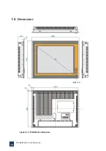
Страница 14: ...TPC6000 6151 User Manual 14 1 6 Dimensions Figure 1 5 TPC6000 6151 dimensions...

Страница 15: ...TPC6000 6151 User Manual 15 Chapter 2 INSTALLATIONS...

Страница 16: ...wristband or similar device The installation steps below should be followed in order Step 1 Unpack the flat panel PC Step 2 Check all the required parts are included Step 3 Install the hard drive Step...

Страница 17: ...following list when you open the package Item Image Quantity TPC6000 6151 1 Touch screen pen 1 Utility CD 1 Power cord 1 Power adapter 1 Mounting Clamps 4 Table 2 1 Packing list If any items are miss...

Страница 18: ...6151 To install the hard drive please follow the steps below Step 1 Flip over this device and you can see its back Step 2 Unfasten the two silver retention screws on the right side Figure 2 1 Figure 2...

Страница 19: ...r as shown in the figure below Step 5 Plant the screw on the HDD bracket Figure 2 3 HDD installation Step 7 Replace the covers and screws 2 4 CFast card installation The installation for a CFast card...

Страница 20: ...TPC6000 6151 User Manual 20 Figure 2 4 CFast card installation Step 3 Replace the HDD bracket cover and screws...

Страница 21: ...the panel PC The following installation options are available 2 6 1 Monitor stand The monitor stand allows the monitor to be used on a desk or table For instructions on installing the monitor stand pl...

Страница 22: ...rely attach the arm to the wall Step 2 Once the mounting arm has been firmly attached to the surface lift the flat panel PC onto the interface pad of the mounting Step 3 Align the retention screw hole...

Страница 23: ...t the rear panel Step 7 Align the mounting screws on the monitor rear panel with the mounting holes on the bracket Step 8 Carefully insert the screws through the holes and gently pull the monitor down...

Страница 24: ...tep 3 Slide the flat panel PC through the hole until the frame is flush against the panel Step 4 Insert the panel mounting clamps into the pre formed holes along the edges of the chassis on the two si...

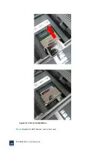
Страница 25: ...igure 2 12 Connectors 2 7 1 LAN connection The RJ 45 connectors enable connection to an extend network To connect a LAN cable with a RJ 45 connector please follow the instructions below Step 1 Locate...

Страница 26: ...w the steps below to connect a serial device to the TPC6000 6151 panel PC Step 1 Locate the DB 9 connector The location of the DB 9 connector is shown in chapter 2 Step 2 Insert the serial connector I...

Страница 27: ...e connector into the onboard connector 2 7 4 VGA monitor connection The VGA output can be connected to an external VGA monitor To connect the VGA monitor to the TPC6000 6151 please follow the instruct...

Страница 28: ...e of the connector 2 8 Power connector The power cable connects the panel PC to power supply The power cable is required for operation of the panel PC Step 1 Connect one end to the panel PC Step 2 Con...

Страница 29: ...B9 COM1 4 defaults RS 232 Open the DIP switch cover set the SW6 SW7 to RS485 through DIP the DIP definitions are Figure 2 17 SW6 SW7 SW6 SW7 RS 232 RS 485 RS 232 RS 485 COM1 1 OFF 1 ON COM3 1 OFF 1 ON...

Страница 30: ...UT you can use it directly Ethernet Interfaces LAN1 LAN2 We provide two 10 100 1000Mbps RJ 45 Ethernet interfaces you can use it directly There are two status indicators links status on the left side...

Страница 31: ...dicator Table 2 7 Indicator of LAN connector CRT monitor interface We provide a standard DB15 monitor interface you can connect it directly Here is the definition 1 6 11 5 10 15 PIN SIGNAL PIN SIGNAL...

Страница 32: ...interface TPC6000 6151 offers a 3 pins power input interface PIN SIGNAL 1 9 30V 2 N A 3 GND Table 2 10 Power connector Switch button PWR We provide a power touch switch button PWR to power up on fron...

Страница 33: ...card audio card display card All drivers program will be store in an optical disc in accessory box That will helps user to install the driver and know the functions Installation steps First step is c...

Страница 34: ...TPC6000 6151 User Manual 34 Double click the Chipset driver program Wait for its loading Press NEXT then go to the next step...

Страница 35: ...TPC6000 6151 User Manual 35 Press YES to agree the License agreement then go to the next step...

Страница 36: ...TPC6000 6151 User Manual 36 Press NEXT to continue Wait for the installation if it done completely then the NEXT key will been set to active then press NEXT to continue...

Страница 37: ...Manual 37 After finish this installation you should restart the computer immediately then you can install other device s driver Select the Yes I want to restart this computer now and press Finish to r...

Страница 38: ...2 10 2 Graphics driver Browse the product s driver disc or D Backup Drivers 2 graphic Win7_32_8 14 1091 you will see the driver file as following figure Double click the graphics driver program Press...

Страница 39: ...TPC6000 6151 User Manual 39 Please select Automatically run WinSAT and enable the Windows Aero desktop theme if supported then press NEXT to go to the next install page...

Страница 40: ...TPC6000 6151 User Manual 40 Press YES to agree the license agreement then go to the next step Press NEXT to go on...

Страница 41: ...TPC6000 6151 User Manual 41 Press YES to agree the License agreement then go to the next step...

Страница 42: ...vice s driver Select the Yes I want to restart this computer now and press Finish to reboot the computer 2 10 3 Audio driver Browse the product s driver disc or D Backup Drivers 3 Audio 32bit_Vista_Wi...

Страница 43: ...TPC6000 6151 User Manual 43 Press YES to continue...

Страница 44: ...t for its installation and after finish this installation you should restart the computer immediately then you can install other device s driver Select the Yes I want to restart this computer now and...

Страница 45: ...User Manual 45 2 10 4 LAN driver Browse the product s driver disc or D Backup Drivers 4 lan Setup exe you will see the driver file as following figure Double click the LAN driver program Wait for pre...

Страница 46: ...TPC6000 6151 User Manual 46 Press NEXT to continue...

Страница 47: ...TPC6000 6151 User Manual 47 All Selected should be installed into the computer then press NEXT Press INSTALL to start this installation and wait for its finished...

Страница 48: ...TPC6000 6151 User Manual 48...

Страница 49: ...TPC6000 6151 User Manual 49 Please click the Install this driver software anyway selection when the Windows security message windows shows And press FINISH to finish the installation...

Страница 50: ...Touch pad driver Browse the product s driver disc or D Backup Drivers 5 Touch RisintechSetup exe you will see the driver file as following figure Double click the touch pad driver program Press NEXT...

Страница 51: ...TPC6000 6151 User Manual 51 Press NEXT to continue Press INSTALL to continue...

Страница 52: ...ter finish this installation you should restart the computer immediately then you can install other device s driver Select the Yes I want to restart this computer now and press OK to reboot the comput...

Страница 53: ...TPC6000 6151 User Manual 53 Chapter 3 BIOS Setup...

Страница 54: ...e DEL key is pressed restarted the computer and try again 3 1 2 Using setup Use the arrow keys to highlight items Press ENTER to select use the PAGE UP and PAGE DOWN keys to change entries Press F1 fo...

Страница 55: ...anges the basic system configuration Advanced Changes the advanced system settings PCI PnP Changes the advanced PCI PnP settings Boot Changes the system boot configuration Security Sets user and super...

Страница 56: ...em Time or System Date using the Arrow keys Enter new values through the keyboard Press the Tab key or the Arrow keys to move between fields The date must be entered in MM DD YY format The time must b...

Страница 57: ...TPC6000 6151 User Manual 57 Figure 3 3 Advanced BIOS Features Setup Screen 3 3 1 PCI Subsystem Setting...

Страница 58: ...TPC6000 6151 User Manual 58 Figure 3 3 1 PCI Subsystem Configuration Setting 3 3 2 ACPI Setting...

Страница 59: ...TPC6000 6151 User Manual 59 Figure 3 3 2 ACPI Configuration Setting 3 3 3 CPU Configuration Setting Figure 3 3 3 CPU Configuration Setting...

Страница 60: ...ual 60 Max CPUID Value Limit This item allows you to limit CPUID maximum value Execute Disable Bit Capability This item allows you to enable or disable the No Execution page protection technology 3 3...

Страница 61: ...TPC6000 6151 User Manual 61 Figure 3 3 4 SATA Configuration SATA E Configuration This item allows you to select Disabled IDE AHCI 3 3 5 USB Configuration...

Страница 62: ...TPC6000 6151 User Manual 62 Figure 3 3 5 USB Configuration 3 3 6 Super I O Configuration...

Страница 63: ...nual 63 Figure 3 3 6 Super I O Configuration Serial Port1 Port4 address This item allows you to select serial port1 port4 of base addresses Serial Port1 Port4 IRQ This item allows you to select serial...

Страница 64: ...TPC6000 6151 User Manual 64 3 3 7 PC Health Status Figure 3 3 7 PC Health status...

Страница 65: ...TPC6000 6151 User Manual 65 3 3 8 PPM Configuration Figure 3 3 8 PPM Configuration EIST...

Страница 66: ...auto adjust operation frequency according to current CPU operation status for power saving consideration This selection item also support the configuration of CPU sleep state support max Intel C6 mode...

Страница 67: ...TPC6000 6151 User Manual 67 3 4 1 Intel IGD configuration Figure 3 4 1 PPM Configuration This selection item mainly for display application configuration...

Страница 68: ...TPC6000 6151 User Manual 68 IGFX Boot Type is for configuration of boot up main display VGA LVDS VBIOS Default 3 5 Chipset settings south bridge Figure 3 5 Advanced Chipset Settings...

Страница 69: ...TPC6000 6151 User Manual 69 3 5 1 NM10 Chip Configuration Figure 3 5 1 NM10 Chip Settings This selection item is for Audio NM10 Chip integrated network card SMBus configuration...

Страница 70: ...TPC6000 6151 User Manual 70 SMBUS Controller Enables or disables the SMBUS controller 3 5 2 PCI Express Port 0 Port 4 Configuration...

Страница 71: ...TPC6000 6151 User Manual 71...

Страница 72: ...TPC6000 6151 User Manual 72...

Страница 73: ...6151 User Manual 73 Figure 3 5 2 PCI Express Port Settings SB PCIE Ports Configuration Intel NM10 chipset support 4 PCI Express x1 bus in which PCIE Port 1 PCIE Port 2 are allocated to onboard LAN1 a...

Страница 74: ...ain Power ON After accidental power off the device will automatically boot up when power on again Last State After accidental power off the device will recover to the state of the former state before...

Страница 75: ...TPC6000 6151 User Manual 75 3 5 4 BOOT Configuration...

Страница 76: ...TPC6000 6151 User Manual 76 3 6 Exit Option Figure 3 6 Exit Option...

Страница 77: ...Changes from the Exit menu and press Enter 3 6 3 Load Optimal Defaults The TPC6000 6151 automatically configures all setup items to optimal settings when you select this option Optimal Defaults are de...

Страница 78: ...TPC6000 6151 User Manual 78 Chapter 4 System Maintenance...

Страница 79: ...ble after opening the rear cover 4 3 Cover Removal Warning Turn off the power before removing the back cover Risk of electrocution Severe damage to the product and injury to the body may occur if inte...

Страница 80: ...TPC6000 6151 User Manual 80 Figure 4 1 Back cover retention screws...

Страница 81: ...TPC6000 6151 User Manual 81 A Safety Precautions...

Страница 82: ...000 6151 chassis is opened when the TPC6000 6151 is running Do not drop or insert any objects into the ventilation openings of the TPC6000 6151 If considerable amounts of dust water or fluids enter th...

Страница 83: ...e only certified engineers should replace the on board battery Dispose of used batteries according to instructions and local regulations Outside the European Union If you wish to dispose of used elect...

Страница 84: ...by A 2 2 Cleaning Tools Some components may only be cleaned using a product specifically designed for the purpose In such case the product will be explicitly mentioned in the cleaning tips Below is a...

Страница 85: ...TPC6000 6151 User Manual 85 B ALC662 Digital Microphone Configuration...

Страница 86: ...k ALC662 HD Audio Manager double click either The Realtek HD Audio Manager icon in the Notification Area of the system task bar Figure B 1 or The Realtek HD Audio Manager icon in the Control Panel Fig...

Страница 87: ...TPC6000 6151 User Manual 87 Figure B 3 Enabling the Digital Microphone Function Step 6 Move the slide bar to adjust the microphone volume Figure B 4...

Страница 88: ...TPC6000 6151 User Manual 88 Figure B 4 Adjusting the Microphone Volume Step 7 Click the Advanced icon Figure B 5 to display the advanced setting screen...

Страница 89: ...TPC6000 6151 User Manual 89 Figure B 5 Mixer ToolBox Screen Step 8 In the Advanced setting screen Figure B 6 the user may turn on the Microphone Boost function Figure B 6 Advanced Setting Screen...

Страница 90: ...TPC6000 6151 User Manual 90 C Watchdog Timer...

Страница 91: ...Timer s period BL Time out value Its unit second is dependent on the item Watchdog Timer unit select in CMOS setup Table C 1 AH 6FH Sub function Call sub function 2 to set the time out period of Watc...

Страница 92: ...PC6000 6151 User Manual 92 INT 15H ADD THE APPLICATION PROGRAM HERE CMP EXIT_AP 1 is the application over JNE W_LOOP No restart the application MOV AX 6F02H disable Watchdog Timer MOV BL 0 INT 15H EXI...

Страница 93: ...TPC6000 6151 User Manual 93 D Hazardous Materials Disclosure...

Страница 94: ...the presences of small quantities of certain materials in the product and is applicable to China RoHS only A label will be placed on each product to indicate the estimated Environmentally Friendly Use...

Страница 95: ...it Board X O O O O X Metal Fasteners X O O O O O Cable Assembly X O O O O X Fan Assembly X O O O O X Fan Assembly X O O O O X Battery O O O O O O O This toxic or hazardous substance is contained in al...

Страница 96: ...TPC6000 6151 User Manual 96 Chapter 5 Appendix A...

Отзывы: