33
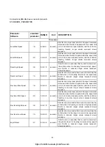
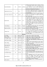
Main Current Limit
90
15 to 90
Ampere
Sets the maximum current the controller will supply to
the motor during 15–90 A normal driving. By limiting
the current supplied, this parameter can be used to
protect the motor from potentially damaging currents
or to reduce the maximum torque applied to the drive
system.
Braking Current Limit
90
15 to 90
Ampere
Sets the maximum current the controller will supply to
the motor during braking. By limiting the current
supplied, this parameter can be used to protect the
motor from potentially damaging currents or to reduce
the maximum braking torque applied to the drive
system.
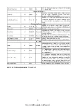
Boost Current
90
90 to 90
Ampere
The Boost Current parameter defines the motor
current limit during the boost period.
Boost Time
3
0 to 10
Seconds
This parameter sets the maximum time that the boost
current is allowed.
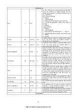
Inhibit menu
Type
2
0 to 5
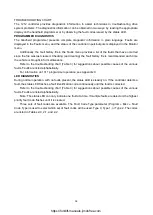
The flexible speed input at J1 Pin 6 can be used to
limit or to inhibit speed under certain conditions. For
example, a switch could be installed under the seat so
that if the operator drives the scooter while they are
standing the max speed will be limited. The Inhibit
Type parameter is used to select how the inhibit
function will be implemented. Depending on how the
inhibit switch is wired into the system, set this
parameter to:
0 = B- active
1 = B+ active
2 = Open circuit active
3 = B- inactive
4 = B+ inactive
5 = Open circuit inactive.
Speed
0
0 to 100
%
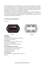
This parameter limits the maximum speed allowed
during speed inhibit mode. A setting of 0 prevents
drive during inhibit mode.
Brake menu
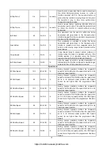
Delay
0.3
0.0 to 1.0
Seconds
Sets the length of delay between when zero speed is
commanded and the electromagnetic brake is
engaged.
Fault Check
1
0 or 1
Enables/disables the fault detection on the EM brake.
Hold Voltage
18
10 to 24
volt
A high initial voltage is applied to the brake coil when
the brake is first released. After approximately 1
second, this peak voltage drops to the programmed
Hold Voltage. The parameter should be set high
enough to hold the brake released under all the shock
and vibration conditions the vehicle will be subjected
to.
Brake Light
0
0 to 1
When set to On, the horn output (J1 Pin 3) will act as
a brake light driver. The brake light must be driven by
a relay
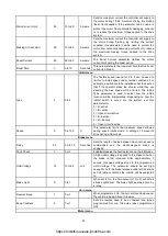
Horn menu
Reverse Beep
1
0 or 1
When programmed On, the horn will sound whenever
the vehicle is being driven in reverse.
Beep Constant
0
0 or 1
Sets the reverse beep to be a constant tone (when
programmed On) or a 1Hz pulse (when programmed
Off).
Motor menu
https://forklift-manuals.jimdofree.com

