background image


7

---LCD Module Set Up--- 

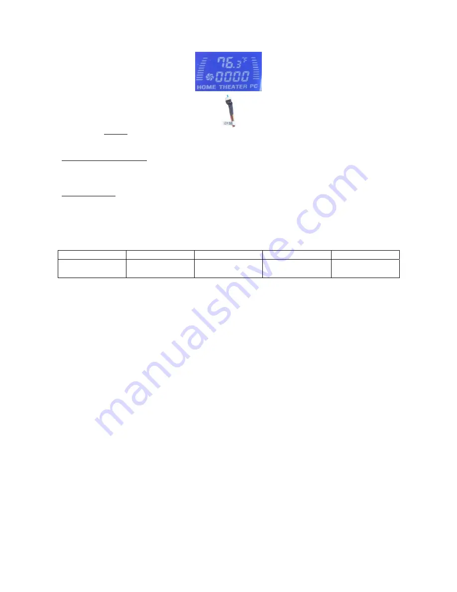
LCD will display the CPU & Case Temp. reading / CPU Cooler Fan Speed reading  


“C/F SW” enables you to set temp display reading format when installing the system. (one time only)


Alarm Features 

CPU Alarm Temperature  
When CPU temperature hits 65ºC or 149F, the temperature reading will flash constantly until the 
temperature drops below the alarm degree. 
 
CPU Fan Alarm  
When the fan stops running for whatever reason during working mode, the CPU fan speed 
reading will flash constantly in “0000” until the fan is re-spinning again. 
 
LCD shows CPU temperature and CPU heatsink fan speed when connecting appropriately. The 
fan speed is automatically adjusted by the CPU temperature. See below chart for more details. 


CPU Temp

Æ


0-86 F 

86 F & up 

104 F & up 

122 F & up 

CPU Fan Spin 
Speed 

70% of full speed  80% of full speed

90% of full speed 

100% full speed 


--Warning-- 

By using 

LCD

 to display CPU Temperature and control CPU Heatsink fan speed, periodically 

check heat sensor placement is required to ensure LCD displays CPU temperature accurately.  
If you don’t feel comfortable to have the LCD to control the heatsink fan speed, just connect the 
fan to the motherboard fan pin connector instead.


Other Component Installation 

For other components, including hard drive; RAM; CPU & cooler; optical drive and operating system 
etc., plan the installation steps carefully, and follow the user manual and motherboard manual 
instruction to avoid damages. 


S/PDIF Output Connection 

It is a standard PC S/PDIF out jack. Connect the header to the onboard S/PDIF output port. See 
below color codes: 

o

  White – “Data” or “S/PDIF out” 

o

  Black – Ground 


Содержание HTPC 300 BA

Страница 1: ...this user guide are the property of their respective owners COPYRIGHT 2006 by NMEDIA SYSTEM INC All rights reserved No part of this publication may be reproduced transmitted transcribed stored in a re...

Страница 2: ...x 1 Air Duct Constant fresh air to CPU and avoid hot air re circulation Front Connectors Onboard headers required o USB 2 0 o IEEE 1394 o Audio Ports LCD Module Tight Cables Screws Installation Guides...

Страница 3: ...priately until your case eject button can eject the tray smoothly then mark down the position and secure the DVD to the DVD rack with screws 6 Remember that installing power supply should always the l...

Страница 4: ...irst find the MIC and GND pin connect the MIC GND connector fist then the SR connector must on the Pin 5 6 face the same label direction of the MIC GND connector plug the SR in same to the SL on Pin 8...

Страница 5: ...ard fan connector In this case the LCD will only display fan speed no fan speed control will be available via the front knob C F SW enables you to set temp display reading format when installing the s...

Страница 6: ...is Step 4 Install Power Supply 1 Take off the two brackets and install the brackets into the power supply screw holes 2 Plug in the extension cord and install the power supply by screwing the two brac...

Страница 7: ...or more details CPU Temp 0 86 F 86 F up 104 F up 122 F up CPU Fan Spin Speed 70 of full speed 80 of full speed 90 of full speed 100 full speed Warning By using LCD to display CPU Temperature and contr...

Страница 8: ...d adjust properly 110 230V Always unplug the power cord before inserting any add on devices Get the system checked by service personnel if below happens The power cable is damage Liquid has penetrated...

Отзывы: