4
(Reference picture only)
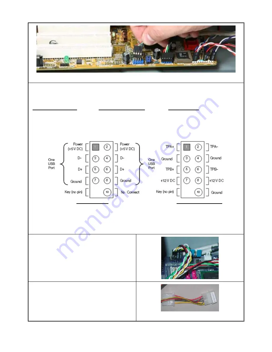
Front USB 2.0, IEEE 1394 and Audio Connectors
See Motherboard User Manual for location and connection.
USB Port Color Codes
:
Red = +5V
White = Data- (-D)
Green = Data+ (+D)
Black = Ground (GND)
IEEE 1394 Color Codes
Black -- Ground (GND)
Red -- +5V
Blue -- +TPB (TPB+)
White -- -TPB (TPB-)
Yellow -- +TPA (TPA+)
Green -- -TPA (TPA-)
Audio Interface
Pin 1 (MIC IN) Red
Pin 2 (MIC GND) Black
Pin 5 & 6 (SR)
Pin 7 (Empty) White
Pin 8 & 9 (SL)
USB Diagram IEEE 1394 Diagram
Front Audio (AC 97) connection Tips:
First, find the MIC and GND pin, connect the MIC & GND connector fist, then, the SR connector must on the Pin
5 & 6, face the same label direction of the MIC & GND connector, plug the SR in, same to the SL on Pin 8 & 9.
Plug the white NC single pin connector to Pin 7.
Note:
There is no HD Audio connector from this model yet.
Connect the Power Button “PWR” & “RESET”
cables to the motherboard front panel jumper
See Motherboard User Manual for location and
connection. And see above referenced picture.
1. Connect the “PWR” LCD power cord to the power
supply like connecting the case fan. This
connection will provide power to:
Power button LCD light
LCD
module
60mm Hard Drive cooling fan


