16
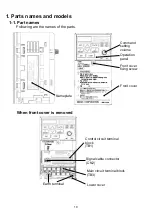
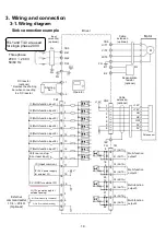
3-2. Description of terminal
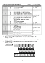
■ Terminal block functionality
Connector specifications of each terminal
Main circuit terminal (TB3) functionality
* While using the DC power, remove the shorting bar b1 and +2, and connect it to N (-) and +1 (+).
Motor sensor input terminal (CN2) functionality
Signal name
Main circuit terminal
Motor sensor input terminal
Control circuit terminal
10
B1
B2
U/T1
V/T2
W/T3
Terminal No.
1
2
3
6
7
8
9
GND
HU
-
Reserved (Do not connect anything)
Signal ground
-
Reserved (Do not connect anything)
N. C
Not used
+12 V
Sensor power +12 V
Pole sensor input
U-phase
Photo-coupler input
HV
Pole sensor input
V-phase
HW
Pole sensor input
W-phase
4
5
+12 V
Sensor power +12 V
GND
Signal ground
Motor drive output
W-phase
Signal name
Details
Remarks
U
Motor drive output
U-phase
V
Motor drive output
V-phase
W
Regenerative resistor connection terminal 1
B2
Regenerative resistor connection terminal 2
T/L3
- (minus)
+1
+2
+1
DC bus voltage (P)
1 and +2
Short circuit (*)
+2
DC bus voltage (P)
T
AC 200 V input T-phase
Connected during single
phase input
N
DC bus voltage (N)
(*)
B1
Terminal No.
R/L1
S/L2
Total 11-pole
10-pole
Remarks
TBET31166-B (6-pole),
TBET31167-B (5-pole)
R
AC 200 V input R-phase
Connected during single
phase input
S
AC 200 V input S-phase
22-pole, plug-in screw
Details
Remarks
Connector type
B10B-PADSS-1
MKKDS1/11-3.5
Connector number
TB3
CN2
TB1
Use
CN2
端子番号
TB3
端子
番号
1
2
10
9
CN2 Terminal No.
TB3 Terminal No.
U/T1 V/T2 W/T3
S/L2 T/L3
+1
R/L1
B1
B2
-
+2
Shorting bar
Содержание A-BLPQ010S2-V2
Страница 1: ...Instruction manual GTR AR Series APQ VER2 Driver...
Страница 27: ...27...
Страница 37: ...37...


