Scrub System
83
Service Manual – SC1500
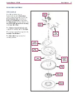
Deck Actuator Assembly
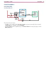
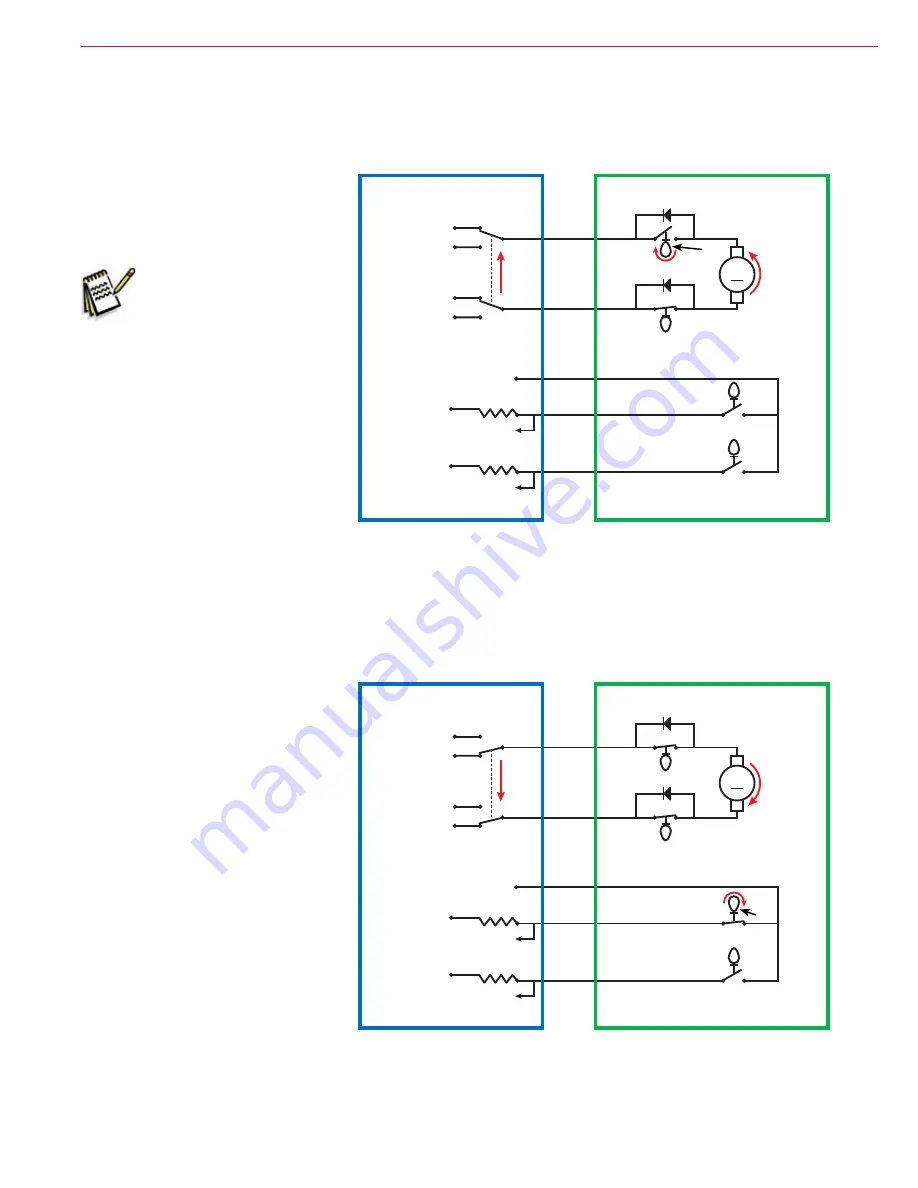
Scrub Deck Up
When the Scrub System is
switched from active to not active,
the
Gang Switch
in the
A1 Control
Board
switches on the power to the
Brush Lift Actuator Motor M3
Note:
The
Gang Switch
position determines the
polarity to run the
Brush
Lift Actuator Motor
in the
appropriate direction to
raise or lower the scrub
deck. The
Gang Switch
is, in reality, a “virtual”
switch that is a type of
transistor driver circuit
in the
A1 Control Board
.
The
Deck Actuator Assembly
raises
the scrub deck until the
Cam
opens
the
Upper Limit Switch
. This shuts
off the power to the
Brush Lift
Actuator Motor
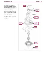
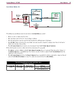
Scrub Deck in Vacuum-only Position
When the Scrub System is not active
and the Vacuum Power Adjustment
Switch is pressed to enable the wet
vacuuming mode, the
Gang Switch
in
the
A1 Control Board
switches on the
power to the
Brush Lift Actuator Motor
M3
. The
Deck Actuator Assembly
lowers
the scrub deck to
POS
(position)
1
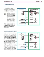
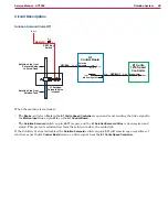
When the deck reaches
POS
1
the
Cam
closes the
S7 POS 1
switch, which
drops the voltage seen at the
Act.
Position 1
input from 5v to 0v. The
Gang Switch
then switches polarity to
run the
Brush Lift Actuator Motor
in the
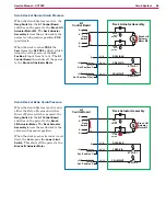
opposite direction for a predetermined
period of time to compensate for
“overshoot” and position the deck at
just the right height. The
A1 Control
Board
then shuts off the power to the
Brush Lift Actuator Motor
M
+5V
B-
J2-11
+5V
J2-12
J1-8
B+
B-
B-
B+
S7 POS 1
S6 POS 2
Upper
Limit
Switch
Cam
Lower
Limit
Switch
A1
Control Board
Deck Actuator Assembly
F BLK/WHT
C RED/VIO
D YEL/BLK
Act. Position 2 (5v)
Act. Position 1 (5v)
Brush Lift
Actuator
Motor M3
Gang
Switch
M
+5V
B-
J2-11
+5V
J2-12
J1-8
B+
B-
B-
B+
S7 POS 1
S6 POS 2
Upper
Limit
Switch
Cam
Lower
Limit
Switch
A1
Control Board
Deck Actuator Assembly
F BLK/WHT
C RED/VIO
D YEL/BLK
Act. Position 2
Act. Position 1 (0v)
Brush Lift
Actuator
Motor M3
Gang
Switch

