Wheel System - Traction
116
Service Manual – SC1500
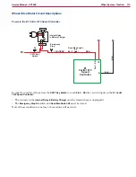
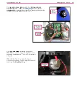
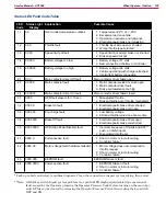
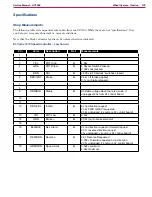
A1 Control Board
Terminal
Speed Controller
Terminal
Function
Status Signal J3-7
Pin 9 - Status (B -)
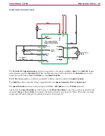
The
Speed Controller
uses the status signal to tell the
A1
Control Board
when it has set a fault, and which fault is set.
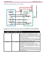
The switch on
Pin 9 - Status (B -)
opens and closes in a pattern
to communicate a specific fault code to
J3-7
. That pattern is
mirrored by the Detergent On/Off Indicator so you can read the
fault.
Like the other circuits, when the switch on
Pin 9
is open, the
signal at
J3-7
is high (24 volts). When the switch on
Pin 9
closes to
B-
, the signal voltage at
J3-7
drops to low (0 volts).
Reverse Alarm J3-5
Pin 16 - Reverse
Alarm (B -)
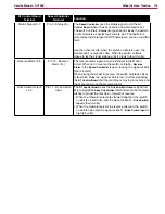
The reverse alarm signal circuit is identical to the Motion
circuit. When not in reverse the switch on
Pin 16 - Reverse
Alarm
in the
Speed Controller
is open, leaving the signal at
J3-5
high (24 volts).
When driving the wheel in reverse, the switch on
Pin 16
closes
to
B -
which drops the signal at
J3-5
to low (0 volts), signalling
the
A1 Control Board
that the machine is moving in reverse and
that it should turn on the Reverse Alarm.
Drive Switch Output
J3-3
Pin 17 - Drive Switch
Input
The
A1 Control Board
uses the
Drive Switch Output
signal from
J3-3
to signal the
Speed Controller
which direction the Operator
wishes to propel the machine – forward or reverse.
•
When the Operator selects the forward direction, the switch
on
J3-3
is closed to
B -
and the signal at
Pin 17 - Drive Switch
Input
is low (0 volts).
•
When the Operator selects the reverse direction, the switch
on
J3-3
is open and the signal at
Pin 17 - Drive Switch Input
is
high (24 volts).

