background image

JAA78851-R.3617.A

- L42-8・ AF-S 17-55/2.8G -

July.11.2005

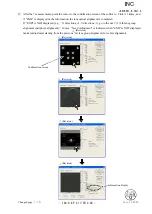
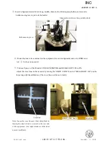
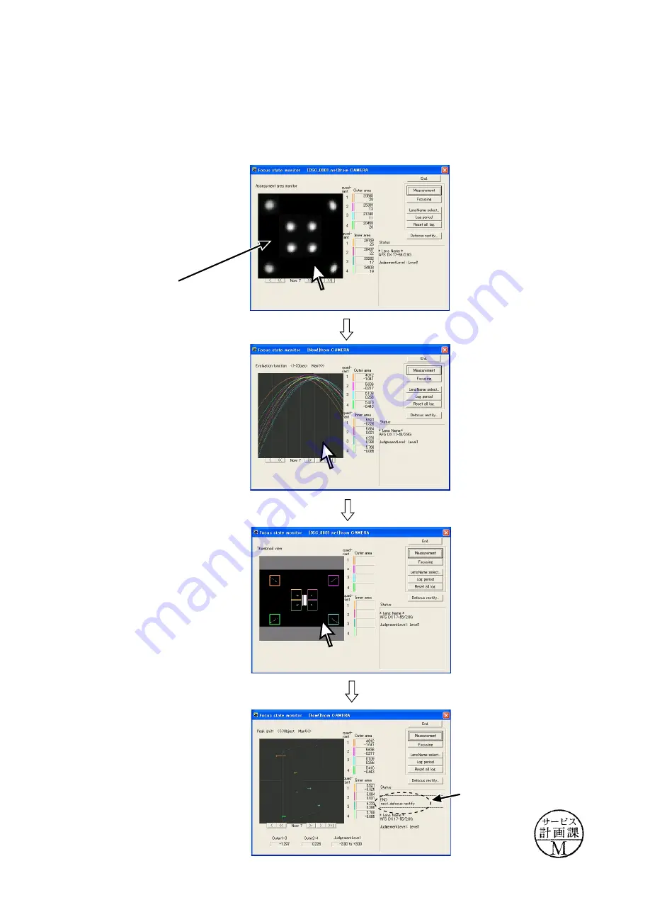
  After the 7 measurements, point the cursor to the confirmation screen of the software.  Click it 3 times, and 

if "END" is displayed on the Information, the lens optical alignment is completed.
If "END" is NOT displayed (e.g. 

X dire1, Y directions:-1), go to the next “(3) 4th lens group 

alignment (periphery alignment)”.  In case  “Need Adjustment” is indicated when "END" is NOT displayed, 
make readjustment starting from the previous “1st lens group alignment (for center alignment).

Information display

Confirmation screen

(Revision)

(Revision)

(Revision)

(Revision)

(Revision)

Changed page

△× 5

INC

Содержание ED 17-55mm f/2.8G IF

Страница 1: ...17 A 作成承認印 配布許可印 NIKON CORPORATION Tokyo Japan Recycled paper Printed in Japan March 2004 Copyright c 2004 by Nikon Corporation All Rights Reserved REPAIR MANUAL AF S DX Zoom Nikkor ED 17 55mm f 2 8G IF JAA78851 INC ...

Страница 2: ...n 10 groups 3 aspherical lens and 3 ED lens elements 79 28 50 with Nikon Digital Camera D1 D1H D1X D100 17 20 24 28 35 45 55mm Output to camera body Manually via separate zoom ring Nikon Internal Focusing IF system utilizing an internal Silent Wave Motor manually via separate focus ring Graduated in meters and feet from 0 36m 1 25ft to infinity 0 36m 1 2ft at all zoom settings Fully automatic f 2 ...

Страница 3: ...sembly Adjustment If the 1st lens group and 4th lens group of this lens are removed lens alignment becomes necessary after assmbling Therefore at service agencies where the lens alignment cannot be performed remove neither the 1st lens group nor 4th lens group INC ...

Страница 4: ... 6 Filter ring 137 1st lens group 49 3 77 Note If the 1st lens group is removed lens alignment of the 1st lens group becomes necessary Therefore at service facilities where the point tester is not prepared do NOT disassemble 1ST LENS GROUP FILTER RING INC ...

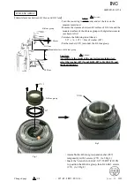
Страница 5: ...lose end and the zoom ring to slightly 35 mm side from 28 mm Assemble J11303B into the cam ring to seat in notches of the cam ring then insert the pin J11303C into the hole of J11303B ref Fig 1 Remove the 2nd lens group with the wrench for 2G AF S 17 35DX J11303A ref Fig 2 Fig 1 J11303B J11303C J11303A Fig 2 INC ...

Страница 6: ...JAA78851 R 3617 A L4 AF S DX17 55 2 8G REAR COVER RING Rear cover ring 182 3 172 4 78 180 2 BAYONET MOUNT INC ...

Страница 7: ... LENS GROUP 71 3 47 4th lens group INDEX RING 128 3 Index ring Note If the 4th lens group is removed the lens alignment becomes necessary Therefore at service facilities where the lens alignment equipment is not prepared do not disassemble INC ...

Страница 8: ... take out 2 screws 96 ref Fig 1 Set the zoom ring to 28 mm and remove the zoom encoder brush ref Fig 2 96 2 Zoom encoder brush Fig 1 ZOOM CONNECTING PLATE 184 2 59 Cam ring Set the zoom ring to WIDE end Take out 2 screws 184 to remove the zoom connecting plate Zoom encoder brush Fig 2 INC ...

Страница 9: ...h through the hole of the zoom ring unit Remove the washer 169 188 2 169 M A selector switch ZOOM RING 67 2 Zoom ring rubber Zoom ring Rear fixed tube Notch Protrusion 131 Zoom ring unit Take out the screw 131 Align the notch of the zoom ring with the protrusion of the rear fixed tube and remove the zoom ring from the rear fixed tube INC ...

Страница 10: ... 55 2 8G AF CONTACT UNIT AF contact unit Remove the AF contact unit from the connector A of the main PCB 200 Peel off the light shielding sheet 200 LIGHT SHIELDING SHEET Tape Remove the tape of the main PCB M A SELECTOR SWITCH A INC ...

Страница 11: ...ck 174 2 173 2 173 2 173 Red Green A B C D 133 134 Fig 2 MAIN PCB Unsolder 2 parts ref Fig 2 Remove 4 connectors A D Take out the screw 133 and 5 screws 173 and 2 screws 174 to remove the main PCB Unsolder 2 parts and remove the M A selector switch ref Fig 1 Fig 1 INC ...

Страница 12: ... ENCODER FPC Zoom encoder FPC Peel off the zoom encoder FPC FOCUS RING Focus ring M A BRUSH M A Brush 49 2 White Yellow Distance encoder brush Remove 2 wires of the distance encoder FPC ref Fig 1 Take out 2 screws 49 to remove M A brush Fig 1 INC ...

Страница 13: ... that fix the wire of the power brush Unsolder 6 wires of the power brush ref Fig 1 Take out 2 screws 49 to remove the power brush B63 at 2 parts Peel off the FPC B3 Take out 2 screws to remove the spring 85 DISTANCE SCALE PLATE 62 2 Distance scale plate Take out 2 screws 62 to remove the distance scale plate SWM White Black Blue INC ...

Страница 14: ... 6 screws 166 to remove the hood fix tube 1ST LENS GROUP STRAIGHT RING 1st lens group straight ring 191 3 192 3 Pull up the 1st lens group straight ring in the direction indicated by the arrow then take out 3 screws 191 and 3 rollers 192 to remove the 1st lens group straight ring INC ...

Страница 15: ...3 AF S DX17 55 2 8G FOCUS SLIDING UNIT 75 2 73 2 Take out 2 screws 75 to remove 2 levers 73 164 130 2 164 80 3 87 3 89 3 116 3 48 52 Take out 3 screws 80 to remove 48 Take out 2 screws 130 to remove 164 ref Fig 1 Fig 1 INC ...

Страница 16: ...the limit in the direction of the arrow so that the roller mounting hole of the cam ring can be seen Take out 3 screws 82 and 3 rollers 90 to remove 52 2 5TH LENS GROUP 81 2 103 2 5th lens group Take out 2 screws 83 and 2 rollers 92 to remove the 2 5th lens group 83 2 92 2 107 81 2 2 5th lens group INC ...

Страница 17: ...JAA78851 R 3617 A L15 AF S DX17 55 2 8G APERTURE BLADE HOUSING UNIT 86 3 91 3 Aperture blade housing unit 3rd lens group 205 102 101 114 3 B47 B9 9 33 B17 106 106 CAM RING GROUP Cam ring 93 2 84 2 INC ...

Страница 18: ...lens body in position FPC Body SWM 161 160 100 2 162 Take out 3 screws 158 and 3 rollers 159 ref Fig 2 Remove the SWM the washer 160 and the wave washer 161 ref Fig 3 Take out 2 screws 100 to remove the SWM connecting key 162 ref Fig 3 Take out the FPC which was put into the lens body 158 3 159 3 Fig 2 Fig 3 Fig 1 INC ...

Страница 19: ...E MOUNTING BASE 61 2 100 2 Magnetic tape unit 72 3 194 3 Stopper screw MAGNETIC TAPE UNIT 124 2 Fig 1 Take out 2 MR head fixing screws 124 ref Fig 1 to prevent damage on the magnetic tape unit Take out 3 screws 72 and 3 rollers 194 to remove the magnetic tape unit Take out the 2 stopper screws Stopper screw INC ...

Страница 20: ...ake out 3 screws 197 to remove the distance encoder FPC Peel off part of the FPC shown by broken line Distance encoder FPC MR HEAD Fixed ring 127 Peel off part of the FPC shown by broken line ref Fig 1 Remove the MR head ref Fig 2 FPC MR head Fig 1 Fig 2 MR head FPC INC ...

Страница 21: ...roken lines DISTANCE ENCODER FPC 197 3 193 2 196 Distance encoder FPC Attach the distance encoder FPC on 196 by aligning it with the screw hole for 193 then tighten 2 screws 193 ref Fig 3 Mount 196 on which the distance encoder FPC was attached on the fixed tube then tighten 3 screws 197 ref Fig 4 Attach the FPC along the broken lines Adhesive Lock end B Fig 1 Fig 2 Fig 3 MR head MR head Adhesive ...

Страница 22: ... In case of disassembling or replacing the MR head be sure to make an adjustment 1 Equipment and tools required Single output rated voltage power supply 1 unit With 5 0V and 100mA applicable to the self made tool Oscilloscope 1 unit Self made tool 1 unit Note In case of any trouble in continuity between the self made tool and the contacts of relay FPC there may be dust corrosion or oxidation on th...

Страница 23: ...se the shape of waveform varies according to the driving speed of magnetic tape unit set Time Div accordingly In case of detecting any wide waveform noise use the filter function How to set the filer function by Yokogawa manufactured DL1540 1 Press the filter button 2 Select Smooth in the menu on the PC screen Setting of oscilloscope V Div CH1 20 mV V Div CH2 20 mV Coupling AC Time Div 5 m Sec Tri...

Страница 24: ...the MR head is regarded as malfunctioning Be sure to replace the MR head unit and adjust it again In case there is a partial drop in the amplitude between the infinity and the near distance the magnetic data of magnetic tape may be damaged Then replace the magnetic tape and adjust it again Turn off the rated voltage power supply In the case of smaller amplitude loosen 2 screws 123 to move the MR h...

Страница 25: ...t with temporarily 2 screws 99 Turn the magnetic tape unit so that the distance between the protrusion and stopper rubber 132 becomes 2 mm ref Fig 1 Adjust so that the contact face of the brush becomes the reference position ref Fig 2 After tightening 2 screws 99 apply Screw lock Magnetic tape unit Protrusion Fig 1 Reference position Adhesive Lock end B Adhesive Screw Lock Magnetic tape unit Fig 2...

Страница 26: ...100 Put the washer 160 and wave washer 161 on Assemble the SWM and engage the shoulder screw of the SWM in the SWM connecting key ref Fig 2 Attach 3 screws 158 and 3 rollers 159 ref Fig 3 Take out the FPC which was put into the lens body Magnetic tape unit Shoulder screw SWM connecting key Fig 2 158 3 159 3 Fig 3 Cam grooves 2 parts Large vertical grooves 2 parts Small vertical grooves 3 parts Gre...

Страница 27: ... 2 APERTURE BLADE HOUSING UNIT 3RD LENS GROUP 3rd lens group 205 102 101 114 3 B47 B9 9 33 B17 106 106 105 104 110 Hook the spring to the assembled aperture blade housing unit at 3 parts ref Fig 1 and Fig 2 Apply the screw lock on both ends of the spring 105 ref Fig 2 Fig 1 33 B17 B47 114 3 101 102 Adhesive Lock end B Adhesive Screw Lock Fig 2 Grease GE 8 INC ...

Страница 28: ... lens group by positioning in the direction of the arrow then fix them with 2 screws 81 ref Fig 1 Assemble the 2 5 lens group to which the levers 103 and 107 were attached into the lens body by aligning each with its notch ref Fig 2 Notch for 103 83 2 92 2 Fig 1 Apply to overall outside 107 81 2 Notch for 107 Adhesive Lock end B Adhesive Screw lock Adhesive Screw lock Adhesive Lock end B Grease MZ...

Страница 29: ...E 8 Adhesive Lock end B Adhesive Screw lock Turn the cam ring in the direction of the arrow all the way almost to the limit so that the roller mount ing hole of the cam ring can be seen Assemble 52 into the lens body at the position where 3 notches circled in Fig 1 and the MR head are located as shown in Fig 1 Attach 52 with 3 screws 82 and 3 rollers 90 Note Be noted that when the screw 82 is atta...

Страница 30: ...straight ring Notch 191 3 192 3 Cam groove at 3 parts Straight grooves at 3 parts MR Head Turn the roller A clockwise to the full up position Adjust so that the notch of the 1st lens group straight ring and the MR head are located at the left position then assemble the 1st lens group straight ring by aligning 3 rollers A with 3 cam grooves of the 1st lens group straight ring Roller A Cam groove B ...

Страница 31: ... the SWM in the direction indicated by the arrow and adjust so that the distance between the protrusion of the magnetic tape unit and the stopper rubber 195 becomes 2 mm ref Fig 2 To leave 2 mm space use a 2 mm diameter drill Adjust the position of the distance scale plate so that the distance scale index and mark are aligned then fix them with 2 screws 62 Fig 1 Fig 2 SWM Distance scale index 61 A...

Страница 32: ...on the FPC B3 ref Fig 3 Fix the wires of the power brush with the tape TA 0012 6mm 20mm Tape TA 0012 White Blue Black Rear side Front side Direction for attaching the spring 85 B63 Long wire M A BRUSH M A Brush 49 2 White Yellow Distance encoder FPC Attach the M A brush with 2 screws 49 Solder 2 wires of the M A brush on the distance encoder FPC ref Fig 4 Fig 4 White Black Blue Adhesive Screw lock...

Страница 33: ...e scale rotates accordingly If the distance scale slips on the way change thickness of the washer 160 ref Page L24 ZOOM ENCODER FPC Zoom encoder FPC Attach the zoom encoder FPC by positioning it in the direction of the arrow MAIN PCB Main PCB Drive PCB 1005 Connect the main PCB and drive PCB with FPC 1005 Put 6 spacers 112 on the main PCB and 2 spacers 111 on the drive PCB 111 2 112 2 112 2 112 2 ...

Страница 34: ...he main PCB as shown in Fig 1 and Fig 2 and fix them with the screw 133 5 screws 173 and 2 screws 174 Connect 4 connectors A D Solder 2 parts ref Fig 3 Put the connector E in position as shown in Fig 4 Fig 1 Fig 2 Fig 3 Fig 4 E M A SELECTOR SWITCH M A Selector switch Blue Black Blue Black A INC ...

Страница 35: ...002 20mm 100mm on the main PCB at the left position Mountain fold Valley fold 200 200 200 LIGHT SHIELDING SHEET Fig 1 Fold the light shielding sheet 200 at the position of Fig 1 to become like Fig 2 Attach the light shielding sheet 200 as shown in Fig 3 10mm Fig 2 Fig 3 INC ...

Страница 36: ... the notch of the zoom ring with the protrusion of the rear fixed ring to assemble them and turn the zoom ring in the direction indicated by the arrow Attach the screw 131 131 Apply overall Apply to the over all inside AF CONTACT UNIT AF Contact unit A Put the FPC of the AF contact unit in the connector A of the main PCB Adhesive Lock end B Grease MZ 800S Grease MZ 800S INC ...

Страница 37: ... Do NOT apply Screw lock on the screw A because it is used for earthing 188 2 ZOOM CONNECTING PLATE 169 M A selector switch 184 2 59 Cam ring Turn the cam ring in the direction indicated by the arrow and stop it slightly short of the limit Set the zoom ring to WIDE end Insert the zoom connecting plate into the hole of the cam ring then fix them with 2 screws 184 Zoom ring unit Adhesive Lock end B ...

Страница 38: ...96 ref Fig 2 Check the position of the brush through the confirmation hole ref Fig 2 and adjust the contact face of the brush so that it becomes the reference position as shown in Fig 3 After the adjustment fix 2 screws 96 with Screw lock Zoom encoder brush 96 2 Reference position Confirmation hole Fig 1 Fig 2 Fig 3 INDEX RING 128 3 Index ring Align 2 indexes Zoom encoder brush Adhesive Screw lock...

Страница 39: ...nder the 4th lens group Caution According to the result of the projection resolution test select the washer 47 from 1K103 087 to 1K103 095 and make adjustment 4TH LENS GROUP Adjust clearance between G10 lens and G11 lens 4th lens group J11305 Assemble the 4th lens group and washer 47 temporarily with 3 screws 71 ref Fig 1 Insert the wrench for 4G AF S 17 55DX J11305 to position the 4th lens group ...

Страница 40: ...aching 165 109 33 101 Fig 2 172 4 78 Put the F F D adjustment washer 78 on the body The opalescent washer should be put on the bayonet side ref Fig 1 Assemble the bayonet at the left position Put the aperture coupling lever 109 in between 101 and 33 ref Fig 2 Fix the AF contact unit with 2 screws 180 Fig 1 180 2 109 Adhesive Lock end B INC ...

Страница 41: ...htly 35 mm side from 28 mm Mount J11303B by aligning with the notches of the cam ring then insert the pin J11303C into the hole of J11303B ref Fig 1 Attach the 2nd lens group with wrench for 2G AF S 17 35 DX J11303A ref Fig 2 Fig 1 38 B8 B11 63 3 The washer 38 should be 0 5 mm fixed in thickness J11303C J11303A Fig 2 1ST LENS GROUP INC ...

Страница 42: ...the 1st lens group then fix them 3 screws 49 Index ADJUSTMENT OF APERTURE DIAMETER J18004 1 Set the zoom ring to TELE side Set the tool J18004 1 and check the aperture diameter Standard Full aperture If it is out of the standard adjust the position of the aperture lever by loosening 2 screws 113 113 2 Aperture lever Adhesive Screw lock Adhesive Screw lock INC ...

Страница 43: ...the thickness of the washer 77 by the value of C calculated in the above If C is positive increase the washers to thicken If it is negative decrease the washers to thin Refer to P L40 Note When putting the washers 77 put a thin washer between thick washers 1 Align the infinity mark of the focus ring with the index 2 Fix the aperture lever so that the aperture becomes full 3 Read the value of Wide ...

Страница 44: ...rture 3 Set the zoom ring to TELE side and the focus ring to 4 Set the lens to the point tester 5 Check the optical axis If it is the case other than Fig 1 loosen 3 screws 63 and adjust G1 lens as shown in Fig 2 6 If it becomes like fix G1 lens with 3 screws 63 63 3 OK NG NG Criteria Fig 1 Optical axis G1 lens Moving direction Point tester Adhesive Screw lock Fig 2 INC ...

Страница 45: ...hape 5 Check the optical axis If it is the case except Fig 1 of the previous page loosen 3 screws 63 and adjust the G1 lens in the direction shown in Fig 2 of the previous page 6 When it becomes as shown in Fig 1 fix the G1 lens with 3 screws 63 3 1st Lens group alignment 1 Position the 4th lens group with the 4th lens alignment tool J11305 ref Page L37 2 Mount the lens to be inspected by aligning...

Страница 46: ... stage Then tighten 4 screws to fix it Create the center positioning tool ref Page42 13 for how to create it Create cardboards in which Lens alignment chart and Viewers are fit ref Page 42 15 for how to create them As for AF S17 55 2 8G the below equipment for center left is NOT used Holder moving lever Move down slowly Holder for 4th lens group J19127L Stage Screw 4 Lens alignment equipment for p...

Страница 47: ...O IN of LINE A Fiber optic cable Cross line chart Pinhole chart Power cable for CCD camera AC power for CCD camera Connect each cable to the appropriate equipment with the same number e g Connect up to Slide rail for Lens alignment equipment Chart shooting equipment for 5th lens group alignment The chart is embeddied in cardboards Changed page 1 Revision INC ...

Страница 48: ...SO to 200 Set up the camera D100 on a tripod on the slide rail Set the indication pointer of the tripod to 30 cm Set the alignment chart J19128 as shown below 30 cm 1 m 80 1 cm Alignment chart J19128 Rail tool Focal plane mark of camera Front Back Turn the power of viewers 5 pcs to ON Note If the batteries of viewers are exhausted with decreased brightness the shooting data cannot be obtained corr...

Страница 49: ...inter of the tripod back to 30 cm Clicking Focusing button activates the AF of camera Fit the lens to be examined in the camera Set the zoom to TELE 55mm By looking through the viewfinder adjust the height and tilt to make the chart fill the entire finder field frame Adjust the tilt of the slide rail to make the 3 chart lines position in the center of the viewfinder when the tripod is slid all the...

Страница 50: ...3617 A L42 6 AF S 17 55 2 8G July 11 2005 Set Focus mode of camera D100 to M Slide the tripod to the front by 18 0 1 cm Click the measurement button of the adjustment software Changed page 2 Revision Revision INC ...

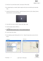
Страница 51: ...tion 4 more times totalling in 7 measurements The total sliding distance is 36 cm Note 1 When the below warning is given there may be some defects in the brightness of the view ers and or parallelism of the chart and camera etc So correct the above and make a remeasurement Note 2 When the below warning is given recheck that the Quality mode of the camera is set to RAW Note 3 When the below warning...

Страница 52: ...optical alignment is completed If END is NOT displayed e g X directions 1 Y directions 1 go to the next 3 4th lens group alignment periphery alignment In case Need Adjustment is indicated when END is NOT displayed make readjustment starting from the previous 1st lens group alignment for center alignment Information display Confirmation screen Revision Revision Revision Revision Revision Changed pa...

Страница 53: ...elease pin Center positioning tool Fixing lever Lens alignment equipment for periphery Unlock the holder moving lever and move the holder down slowly by the lever Holder moving lever Unlock Move down slowly Adjust the holder s position by rotating the micrometers for X axis or Y axis so that the holder does not touch the protection ring of the center positioning tool Note Without this alignment th...

Страница 54: ... of MEGALIGHT 100 and the focus ring until the calibration of the cross lines can be seen clearly LIGHT CONT knob Focus ring Cross line Note In case the cross lines are tilted adjust them by turning the chart which is screwed in the rear tube of the equipment Just slight slackness of the chart poses no problems Insert 3 alignment screwdrivers long middle short in the 4th lens group holder and move...

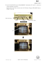
Страница 55: ...of LINE GENERATOR Turn the knobs of X1 and Y1 so that X and Y lines are displayed on the monitor Superpose these X and Y lines on the cross lines of the CCD camera Then press LINE LOCK button to fix these X and Y lines LINE GENERATOR X1 knob Y1 knob LINE ON OFF button LINE LOCK button Y line X line INC ...

Страница 56: ...rections 1 Y directions 1 Pic 1 Fix the 3 screws of the 4th lens chamber with the alignment screwdrivers Move the holder moving lever up to lock the holder Check that a shift length caused by the cross lines and the X Y lines is equal to the scales 1 1 scale of the calibrated cross lines of the results of Chart shooting of the 4th lens group alignment ref Pic 1 Note After fixing the 3 screws of th...

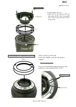
Страница 57: ...ich the lock pin of camera bodyenters just upward Fig 1 3 2 Mount the reversed rearcover ringon thepositionof Fig 1 and attach themas shown in Fig 2 Put with the groove in which the lock pin of camerabodyenters just upward Large notch of rear cover ring Fig 2 How to create positioning tool of 4th lens group holder for lens alignment AF S DX ED 17 55 2 8G It is the same tool with AF S ED 24 85 3 5 ...

Страница 58: ... Then stop at the position as shown inFig 3 1 Fig 3 Fig 3 1 3 4 Fixthefollowing3locationsof the rearcover ring with theinstant adhesive Fig 4 3 5 Turn the bayonet mount over Reinforcethe following 3locations with the adhesive to attach the bayonetmountandrear cover ring firmly 3 6 Attachthemount rotation stopper screwat the appropriate position INC ...

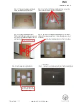
Страница 59: ...he shape at 5 locations shaded parts size 154 x 245 mm as shown below ref Fig 2 Note Cutting the shape slightly smaller than the actual size of viewers makes it easier to fit the positions of viewers tightly 3 2 Put the 2nd flattened cardboard box size 2 33 and the above cut out 1st cardboard together as one and fix them by taping at 4 sides ref Fig 3 3 3 Then as for the 2nd flattened cardboard bo...

Страница 60: ... cardboard box cut out the 154 x 245 mm sized shape at 5 locations Fig 4 As for the 2nd flattened cardboard box cut out the shape in the same way as Fig 2 All cardboards are cut out as below Fig 1 Prepare 2 package cardboard boxes and flatten them as below Put the 2nd flattened cardboard boxe and the 1st cut out cardboard together as one as shown below To prevent viewers falling off secure the vie...

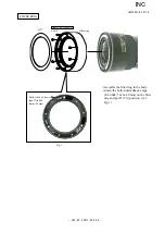
Страница 61: ... Filter ring 137 Both sided adhesive tape TA 0004 5mm 10mm Assemble the filter ring in the body Attach the both sided adhesive tape TA 0004 5 mm 10 mm on the filter ring and put 137 in position ref Fig 1 Fig 1 Adhesive Lock end B FILTER RING INC ...

Страница 62: ...cessary adjustments as follows 1 Adjustments Adjust the MR duty Adjust the driving frequency and motor control 2 Equipment and tools to be required Single output rated voltage power supply 1 unit 6 0V 3 0A Oscilloscope 1 unit For adjusting the MR duty the driving frequency and motor control AF I communication box J15306 1 1 unit AF I communication adapter J15307 1 unit INC ...

Страница 63: ...sion connector RJ does not supply this connector Use products on the market AF S DX zoom 17 55 2 8G inspection and adjustment software J18364 Personal computer This system does not depend on the CPU type of personal computer AF I communication adapter J15307 To RS232C terminal AF I communication box J15306 1 Oscilloscope Power supply 6V Remove the rear cover ring of the lens INC ...

Страница 64: ...nstructions on the screen rotate the MF ring from the near distance to the infinity to the near distance direction slowly by hand Make sure that the waveform on the oscilloscope has duty 50 and then stop the MF ring at the near distance end Setting of oscilloscope V Div CH1 5V V Div CH2 5V Coupling DC Time Div 5 m Sec Trigger Mode NORMAL Trigger Coupling DC Trigger Source CH 1 Trigger Position 4 d...

Страница 65: ...rn on the rated voltage power supply Select ADJUSTMENT FOR DRIVING FREQUENCY MOTOR CONTROL in the menu items of the AF S DX zoom 17 55 2 8G inspection program The lens starts scanning automatically When the abobe display apears and the motor stops driving select Yes Y to end the djustment If the motor does not stop driving select No N to make the adjustments again If the afjustment is done again b...

Страница 66: ...the oscilloscope In case the irregularity of mechanical operations does not take place in the focus ring driving unit the servo time tends to be long if it is heavy in the cam ring rotation of the MR encoder while the servo time tends to be short if it is light in its rotation of the MR encoder 4 Check of switches and lenses Check the ON OFF operations of switches the distance encoder and zoom enc...

Страница 67: ...display the inspection start display etc appears The displays are differrent depending on the items Follow the instructions of a personal computer Operating voltage Power supply for AF motor inside lens Power supply for AF I communication box Inspection of MR encoder operation 6 0 0 1 V Inspection of lens servo stop accuracy 6 5 0 1 V 5 5 0 2 V Inspection of lens servo time 6 5 0 1 V Inspection of...

Страница 68: ...value is shown the pulses Do NOT touch the MF ring during operations Execute inspection for the 5 positions as below Lens inclination Position of index window Horizontal Up right and left Front lens group 90 upward Front lens group 90 downward Lens position in inspecting When the inspection is ended the inspection result appears in the next page INC ...

Страница 69: ...st be within the standard Standard of the total pulses 4044 125 PLUSE S TYPE OF LENS AF S 17 55mm 2 8G DX CPU VERSION 2 01 00 THE TOTAL NUMBER OF PULSE S AT INSPECTION PULSE S 4044 STANDARD FOR THE TOTAL PULSE NUMBER FROM 3919 TO 4169 PULSE S IN STANDARD PUSH OK TO RETURN TO MENU OK INC ...

Страница 70: ...5 0 00 Df6 0 00 RATIO 2 Df1 0 00 Df2 0 00 Df3 0 00 Df4 0 00 Df5 0 00 Df6 0 00 PUSH CANCEL TO RETURN TO FOCAL DISTANCE SET UP MENU Caution If the MF ring is rotated while the lens scanning is driven the pulse shows an abnormal value Do NOT touch the MF ring during operations During the lens driving the above screen is displayed Make inspections at the 5 positions as below Lens inclination Position ...

Страница 71: ...the delay time msec millisecond to prevent stopping the lens into the entry field of DELAY TIME of the below Note The value of ADUST DELAY TIME is set by the adjustment software So if the lens does not stop during the inspection of LENS DRIVING STOP ACCURACY any value can be input without problem However the larger the value of ADJUST DELAY TIME gets the longer the inspection time becomes INC ...

Страница 72: ...drive time must be within the standard Caution If the MF ring is rotated during inspections the waveform shows an abnormal value Do NOT touch the MF ring during inspections Make inspections at the 5 positions as below Lens inclination Position of index window Horizontal Up right and left Front lens group 90 upward Front lens group 90 downward Lens position in inspecting E terminal H terminal E ter...

Страница 73: ...he lens driving mode selector The status of Switches TYPE OF LENS AF S 17 55mm 2 8G DX CPU VERSION 2 01 00 FOCUSING ENCODER 0 1 17 0 2 18 1 0 3 18 2 0 4 1 2 3 4 5 6 7 8 9 10 11 12 13 14 15 16 ZOOMING ENCODER 0 1 18 0 2 19 0 3 20 1 21 2 22 3 23 4 5 6 7 8 9 10 11 12 13 14 15 16 17 SWITCHS AND LENS CONDITION FOCUSING ENCODER 0 1 ZOOMING ENCODER 0 LENS DRIVING MODE SELECTOR M A PUSH CANCEL TO RETURN T...

Страница 74: ...ens part glass lens chamber is replaced or when each lens part is disassembled Be sure to make this adjustment after completing inspecting and adjusting the main PCB 1 Preparation Test chart Self made tool ref Procedure for how to create it Tripod D100 Personal computer USB cable UC E4 Adjustment software LWM exe used for the lens optical alignment 2 Procedure for how to create Test chart Photocop...

Страница 75: ...JAA78851 R 3617 A L54 2 AF S DX17 55 2 8G Additional page November 4 2004 Target chart Resolution chart INC ...

Страница 76: ...et and ISO to 200 Set up the camera D100 in which the lens to be inspected is fit on the tripod Set the focal length to 55 mm and the distance between the test chart and camera CCD face to 2 m 20 2 cm Test chart 2 m 20 2 cm As shown below bring the target chart in the center of focus area within viewfinder Target chart Within viewfinder Resolution chart Connect the PC and camera via USB cable Came...

Страница 77: ...er is released after the AF operation The shot image is automatically displayed on the PC screen Scale the image to 100 and check which chart is in focus of the 5 resolution charts 100μm 100μm 50μm 50μm 0μm Input the value of the focused position into the entry field e g The below is the case when 100μm of the front focus side is in focus INC ...

Страница 78: ...rform the operations from to of the previous page Set the focal length of the lens to 17 mm and the distance between the test chart and camera CCD face to 68 2 cm Perform the operations from to of the previous page Check that the values of all the focal lengths are displayed within the dotted red circle Then click on Rewriting When A compensation value is written in is displayed click OK INC ...

Страница 79: ...the value that was written in EEPROM is not reflected on the results of shooting When the adjustment software restarts perform the operations from to again Check that 0μm of the AF position is in focus It is also possible after Wide side shooting of to take the Middle side shooting of and the Tele side shooting of If 0μm is not in focus repeat the operations from to If it is not still in focus eve...

Страница 80: ... listed below Some adjustment may be requared Parts Replaced Item of Adjustment Adjustment for MR duty Necessary to write fixed value Adjustment for frequency control Inspection and adjustment for the waveform output from MR encoder Main PCB SWM MR HEAD UNIT INC ...

Страница 81: ...MATOR LT 500S LENS ADAPTER FOR FOCUS TESTER INSPECTION AND ADJUSTMENT SOFTWARE FOR AF S ZoomDX17 55 2 8G AF I COMMUNICATION BOX AF I COMMUNICATION ADAPTER PERSONAL COMPUTER POWER SUPPLY OSCILLOSCOPE WRENCH FOR 2ND LENS GROUP SUPPORT TOOL FOR 2ND LENS GROUP SUPPORT TOOL PIN FOR 2ND LENS GROUP WRENCH FOR 3RD LENS GROUP WRENCH FOR 4TH LENS GROUP POINT TESTER SELF MADE TOOL TOOLS Note Use the self mad...

Страница 82: ...own below Make a self made tool according to this procedure This tool is the same one that was made for AF S24 85 3 5 4 Use the same main PCB that was used for AF S24 85 3 5 4G Remove the mounted parts elements condenser transistor IC etc from both sides of PCB within the range of the left dotted lines Do not remove the connec tor Cut off the PCB along the dotted lines Solder the wires on the PCB ...

Страница 83: ...JAA78851 R 3617 A F1 AF S DX17 55 2 8G 外観図 Sketch drawings 110 5 φ 85 5 INC ...

Страница 84: ...JAA78851 R 3617 A F2 AF S DX17 55 2 8G 組立図 Structure of the Lens INC ...

Страница 85: ...基板 裏面 SWM PCB Rear side メイン基板 裏面 Main PCB Rear side ズームエンコーダFPC Zoom encoder FPC 接点 FPC Contact FPC メイン基板 Main PCB SWM基板 SWM PCB SWM 磁気テープ Magnetic tape MR FPC SWM FPC M A Switch はんだブリッジ Solder bridge White Yellow 黒 青 青 黒 白 黒 白 青 緑 赤 Green Red Blue B l u e B l a c k W h i t e B l a c k W h i t e B l a c k B l u e INC ...

Отзывы: