


20
CONNECTIONS
Installation guide Powerdrive MD Smart Equipment
5704 en - 2021.10 / b
2
AI1+
Differential analog input 1 (+)
3
AI1-
Differential analog input 1 (-)
Factory setting
0-10V speed reference
Input type
± 10 V differential bipolar analog
voltage (for common mode,
connect terminal 3 to terminal 6)
Absolute maximum voltage
range
± 36 V
Voltage range in common mode ± 24 V/0 V
Input impedance
> 100 kΩ
Resolution
11 bits + sign
Sampling period
2 ms
Input filter bandwidth
~ 200 Hz
4
AI2+
Differential analog input 2 (+)
5
AI2-
Differential analog input 2 (-)
Factory setting
4-20 mA speed reference
Input type
Unipolar current
(0 to 20 mA, 4 to 20 mA,
20 to 0 mA, 20 to 4 mA)
Absolute maximum current
30 mA
Voltage range in common mode ± 24 V/0 V
Input impedance
100 Ω
Resolution
12 bits
Sampling period
2 ms
Input filter bandwidth
~ 200 Hz
6
0V
Analog circuit common 0 V
The 0 V on the electronics is connected to the metal ground of the
drive
7
AI3
Analog input 3
Factory setting
No assignment
Input type
± 10 V bipolar analog voltage
in common mode or unipolar
current (0 to 20 mA, 4 to 20 mA)
Resolution
11 bits + sign
Sampling period
2 ms
Input filter bandwidth
~ 200 Hz
Voltage range in common mode ± 24 V/0 V
Voltage mode
Input impedance
> 50 kΩ
Absolute maximum voltage
range
± 30V
Current mode
Input impedance
100 Ω
Absolute maximum current
30 mA
3.2 - Connection of the control
• The Powerdrive MD Smart inputs have a positive
logic configuration. Using a drive with a control
system which has a different control logic may cause
unexpedted starting of the motor.
• The Powerdrive MD Smart control circuit is isolated
from the power circuits by single insulation. Its electronic
0V is connected to the connection terminal on the outer
protective conductor (earth terminal). The installer must
ensure that the external control circuits are isolated
against any human contact.
• If the control circuits need to be connected to circuits
complying with SELV safety requirements, additional
insulation must be inserted to maintain the SELV
classification (see EN 61140).
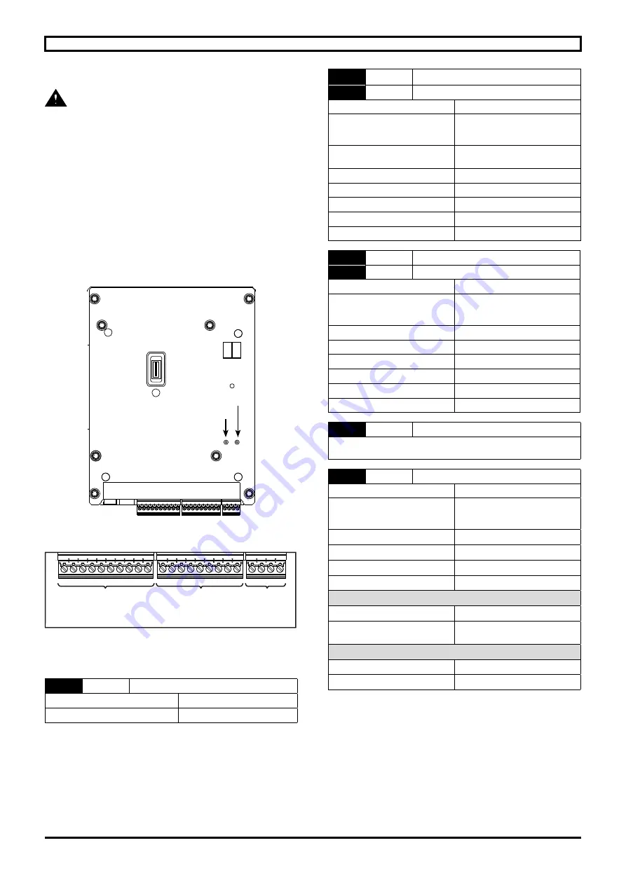
3.2.1 - Control terminal block location
Px1
Px2
Px3
P1 P2
1
1
1
RL2 LED status relay
RL1 LED status relay
Control terminal blocks
Px1
Px2
Px3
1
1
1
Control terminal block
Plug-in screw terminal block:
tightening torque
= 0.3 N.m/0.22 Ib ft
cross-section
= 1.5 mm
2
screwdriver
= flat 2 mm
Analog
inputs/outputs
Digital
inputs/outputs
Relay
3.2.2 - Control terminal block characteristics
3.2.2.1 - PX1 terminal block characteristics
1
10V
+10 V internal analog source
Accuracy
± 2%
Maximum output current
10 mA


