


XR67
6
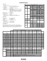
SPECIFICATIONS
ELECTRICAL
A. Operating Power (Vin)
1. Volts .............................See Line Driver Option Chart
2. Current .........................Each output, 100mA Nom. 355mA Max.
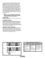
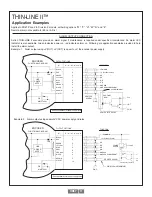
B. Output Format
1. 2/ & Comp ....................A, A, B, B (differential line driver)
2. Marker ..........................1/Rev, Z, Z
C. Signal Type ......................Incremental, Square Wave, 50 ±10% Duty Cycle.
D. Direction Sensing.............Typically A leads.
................................
Refer to the connector pinout and phasing table for
................................
exceptions B for CW rotation as viewed from the
................................
back of the tach looking at the non-drive
end of
................................
the motor.
E. Phase Sep .......................15% minimum
F. Frequency Range ............0 to 165,000 Hz
G. PPR ................................8-5000
H. Line Driver Specs ............See table
I. Connectors.......................See connector options on page 1
J. Integral LED Indicator ......GREEN: power on, unit ok. RED: alarm on
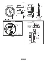
MECHANICAL
A. Rotor Inertia .....................0.17-0.36 Oz. In. Sec.2
B. Acceleration .....................5000 RPM/Sec. Max.
C. Speed ..............................5400 RPM Max.
D. Weight ..............................2-3 lbs [0.9kg to 1.36kg].
E. Sensor to Rotor
Air Gap (nominal).............0.023” [0.58mm]
Tolerance .........................±0.015” [0.38mm]
F. Rotor Axial Tolerance........±0.050” [±1.27mm]
ENVIRONMENTAL
Solid cast aluminum stator and rotor. Less than 7.5% in total magnesium,
titanium and zirconium. Fully potted electronics, protected against oil and water
spray. Operating Temperature: -40 to 80°C, 0-100% condensing humidity. See
“Description” section for information on hazardous location environments.
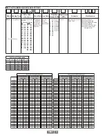
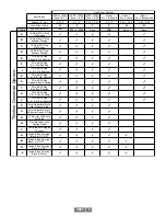
Line Driver Specifica.ons
Isolator Specifica.ons
Code
H
5
7
F
G
XRB1
XRB2
Descrip.on
Symbol
ATEX / IECEx Zone
1 & 21(ia)
ATEX / IECEx
Zone 1 & 21(ib)
ATEX / IECEx
Zone 2 & 22
Class I
Div. 1 & Zone 0
Class I
Div. 2 Listed
ATEX / IECEx Zone
1 & 21(ib)
ATEX/IECEx Zone
1&21(ia) + Class I Div
1&Zone 0
Units
Line Driver
7272
7272
7272
7272
7272
IXDF604
IXDF604
Input Voltage (Nominal)
V
IN
/ V
S
5-‐7
5-‐7
5-‐24
5-‐7
5-‐24
12-‐24
12-‐24
V
DC
Input Voltage (Max Safe)
U
M
N/A
N/A
N/A
N/A
N/A
30
30
V
Input Current (no load)
I
IN
/ I
S
80
80
80
80
80
150
150
mA
Input Current (Typical)
I
IN
/ I
S
100
100
200
100
200
450
450
mA
Input Current (Max.)
I
IN
/ I
S
140
140
300
140
300
900
900
mA
Output Voltage (nominal)
V
H
N/A
N/A
N/A
N/A
N/A
6.8
6.8
V
DC
Output Voltage Min.(@140mA)
V
H
N/A
N/A
N/A
N/A
N/A
5
5
V
DC
Output Voltabe Max(No Load)
V
H
N/A
N/A
N/A
N/A
N/A
7.14
7.14
V
DC
Output Current (@6.8V)
I
H
N/A
N/A
N/A
N/A
N/A
115
115
mA
Output Current (@5V)
I
H
N/A
N/A
N/A
N/A
N/A
140
140
mA
Output Current (short circuit)
I
H
N/A
N/A
N/A
N/A
N/A
420
420
mA
Voltage Output High (Nominal)
V
OH
5
5
V
IN
-‐1
5
V
IN
-‐1
10.6
V
S
-‐1
V
DC
Voltage Output Low (Nominal)
V
OL
.5
.5
.5
.5
.5
.4
.4
V
DC
Signal Current (Con.nuous)
I
OH
/ I
OL
100
100
100
100
100
250
2580
mA
Signal Current (Peak)
I
OH
/ I
OL
1500
1500
1500
1500
1500
3000
3000
mA
Output Resistance Ω
R
OH
/ R
OL
15
15
15
15
15
7
7
Ω
Cable Drive
500
500
5-‐15Vin=500
24Vin = 250
500
5-‐15Vin=500
24Vin = 250
1000
1000
d.
Protec.on
Reverse Voltage
Yes
Yes
Yes
Yes
Yes
Yes
Yes
Short Circuit
Best
Best
Good
Best
Good
Best
Best
Transient
Good
Good
Good
Good
Good
Best
Best
Alarm
+Vout
no
no
Yes
no
Yes
no
no
Alarm
no
no
Yes
no
Yes
no
no
LED
Yes
Yes
Yes
Yes
Yes
no
Yes
+Vout
Reverence Signal for Alarm Circuit, Output Voltage = Input Voltage
Alarm
Open Collector, normally off, goes low on alarm, sink 100mA max, See Connector Pinouts for Availability
LED
Green = Power On, Red = Alarm
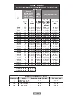
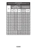
XR67 Connector Spare Parts
Style
Code
Encoder Side
Customer Side
Small
Industrial
"Epic"
P, G
315934
Base
315937
Hood
315935
Terminals
315936
Terminals
401122 1/2 NPT
10 pin MS A, B, C,
D
Box Recepticle
Plug
315933
Standard
315932
Standard
431079
Line Driver "R"
316445
Line Driver "R"
411216
Bushing
411217
Bushing
411218
Bushing
411219
Bushing
7 Pin MS E, F, J, K,
S, T, U, V
Box Recepticle
Plug
316297
Standard
315932
Standard
431080
Line Driver "R"
316446
Line Driver "R"
411218
Bushing
411219
Bushing
Conduit
Box
H,M,N,8
364987
Terminal Plug
10 pin
mini MS
Twist
Lock
R
431081
Base
316447
Plug
471748
Gasket
10 pin MS
on cable
Y
314383
In-Line
316445
Plug
411216
Bushing
411217
Bushing
411218
Bushing
411219
Bushing
Содержание Avtron SMARTSafe XR67
Страница 13: ...XR67 13...
Страница 14: ...XR67 14...


