


XR67 11
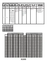
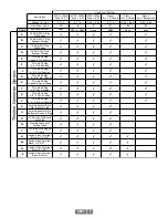
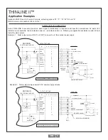
Applies to XR67 Zone 2 & Division 2 models, with wiring options “W”, “P”, “H”, “M”,“N”, and “8”.
Remote alarm not available for Zone I & Div I
ALARM OUTPUT CONNECTION
Avtron THIN-LINE II encoders provide an alarm signal if maintenance is required under specific circumstances. An alarm LED
indicator is also available. Green indicates power on, red indicates alarm on. Following are application examples provided to help
install the alarm output.
Example 1. Alarm output using +V(OUT). +V(OUT) is equal to +V, the encoder power supply.
THIN-LINE II™
Application Examples
BLACK
RED
GREEN
YELLOW
BLUE
GRAY
ORANGE
WHITE
BROWN
VIOLET
OUTPUT
OPTIONS
9
4
5
10
2
8
3
7
6
1
Vcc
OUT
COM
300 OHM
MIN.
GND
REMOTE
ALARM
REMOTE ALARM
FUNCTION
ENCODER
ØB
ØA
ØA
ØB
SOLID STATE RELAY
Q5
MMFT6661
LINE
DRIVER
NOTE 1
CR8
{
FUNCTIONAL DIAGRAM
50 mA MAXIMUM
“W”
MARKER
MARKER COMPLEMENT
COMMON
+V (Encoder Power)
*See specifications for power supply limits
*See specifications for power supply limits
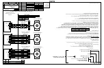
Example 2. Alarm output using seperate *VDC power supply and relay.
{
BLACK
RED
GREEN
YELLOW
BLUE
GRAY
ORANGE
WHITE
BROWN
VIOLET
OUTPUT
OPTIONS
MARKER
MARKER COMPLEMENT
GND
FUNCTION
+V (Encoder Power)
COMMON
*
VDC
+
-
POWER
SUPPLY
115 VAC
SINK 100 mA MAXIMUM
Q5
MMFT6661
ENCODER
FUNCTIONAL DIAGRAM
ØB
ØA
ØA
ØB
LINE
DRIVER
NOTE 1
CR8
“W”
Vcc
OUT
COM
300 OHM
MIN.
4-16 VDC SOLID STATE RELAY
“P”, “H”, “M”, “N”, and “8”
9
4
5
10
2
8
3
7
6
1
“P”, “H”, “M”, “N”, and “8”
Содержание Avtron SMARTSafe XR67
Страница 13: ...XR67 13...
Страница 14: ...XR67 14...


