Nidec Avtron SMARTSafe XR67 Скачать руководство пользователя страница 3

XR67

3

If the alarm output and/or LED indicate a fault (RED) on a properly 

mounted XR67 and the rotor is properly located, replace the XR67.

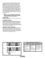
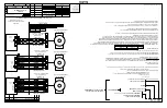
An oscilloscope can also be used to verify proper output of the 

SMARTSafe™ encoder at the encoder connector itself and at the 

drive/controller cabinet. If the outputs show large variations in the 

signals at steady speed (jitter or “accordion effect”, see figure below), 

check rotor position. If the rotor position is correct, the motor or 

shaft may be highly magnetized. Replace any magnetized material 

nearby with non-magnetic material (aluminum, stainless) (especially 

shafts). For GE CD frame motors and similar styles, Avtron offers 

non-magnetic stub shafts. If variations persist, consider replacing 

the encoder with super-shielded models, option -005, or use retrofit 

shielding kits AVSKxxx yy z, where xxx=model (ex: 67A), yy=rotor (ex: 

CB), and z=cover (ex: F).

 NOTE:


Do not use rotors from THIN-LINE I (M56, M56S, M67,  


M85, M115) with XR67  This will cause incorrect PPR 


output, but the XR67 LED will remain green.
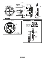
ENCODER REMOVAL

The XR67 stator housing can be removed by loosening and removing 

the socket head cap screws.

CAM SCREW ROTOR REMOVAL

Disengage the (2) cam screws by turning them counterclockwise 

less than 1 full turn. The cam heads will visibly move away from the 

shaft. Remove the rotor by hand by pulling it away from the motor. If 

the rotor will not move, do NOT use a gear puller, and do not use a 

heat gun. Instead, insert two M6 screws, >25mm length into the Jack 

Screw Holes shown in Fig 2. Alternately tighten the screws to push the 

rotor away from the motor and remove it.

LARGE BORE SET SCREW ROTOR REMOVAL

Disengage the (2) set screws by turning them counterclockwise until 

removed from the rotor. Retain the set screws. Remove the rotor by 

hand by pulling it away from the motor. If the rotor will not move, do 

NOT use a gear puller, and do not use a heat gun.  Instead, pry the 

rotor away from the motor gently, being careful to only pry against the 

rotor metal hub and not the magnetic outer strip.

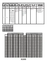
Equipment Needed for Installation 

Provided

Optional

Not Provided

XR67 Stator/Housing

Socket Hd Cap Screw 

3/8”-16 x 1.00” (4)

XR67 Rotor

Socket Set Screw

#M4 x 8mm (2) or Pre-

Installed Cam Screw

Thread locker (blue)

Extended Shaft Cover 

w/ Screws 6-32 x 

0.31” (4)

Lock Washers

Thru-Shaft Cover 

    w/ V-Ring Seal and  

   Silicone Lubricant

Phillips Screwdriver

2mm Hex Wrench 

(T-Handle Style for Set 

Screw Style Rotors)

3mm Hex Wrench

5/16” Hex Wrench

VARIATION > ± 15%

PHASE A

PHASE B

Содержание Avtron SMARTSafe XR67

Страница 1: ...uitable for connection into a safety system The XR67 construction materials contain no more than 7 5 in total by mass of magnesium titanium and zirconium These materials are not considered as able to...

Страница 2: ...rTM encoders with a cable shield connection on pin 10 Note that this option does not ground the shield CORRECTIVE ACTION FOR PHASE REVERSAL 1 Remove Power 2 Exchange wires on cable either at encoder c...

Страница 3: ...CREW ROTOR REMOVAL Disengage the 2 cam screws by turning them counterclockwise less than 1 full turn The cam heads will visibly move away from the shaft Remove the rotor by hand by pulling it away fro...

Страница 4: ...DP 52mm TS 2 625 DR 55mm TU 2 875 DS 60mm TV 3 000 MU 65mm T4 3 125 MV 70mm T7 3 188 MW 75mm MY 80mm MZ 85mm E Extended Shaft Cover F Flat Cover T Flat Thru Hole Cover with Shaft Seal See Line Driver...

Страница 5: ...E 7 Pin MS W Plug A quad B Std Phasing F 7 Pin MS W Plug A A Std Phasing J 7 Pin MS W Plug A B Z Std Phasing K 7 Pin MS W Plug A A B B Std Phasing S 7 Pin MS W Plug A quad B Dyn Phasing T 7 Pin MS W...

Страница 6: ...100 100 200 100 200 450 450 mA Input Current Max IIN IS 140 140 300 140 300 900 900 mA Output Voltage nominal VH N A N A N A N A N A 6 8 6 8 VDC Output Voltage Min 140mA VH N A N A N A N A N A 5 5 VD...

Страница 7: ...CT AVTR2 TT A36521 TT A36523 TT 1 625 1 6245 CJ AVTR1 CJ AVTR2 TJ A36521 TJ A36523 TJ 1 750 1 7495 CK AVTR1 CK AVTR2 TK A36521 TK A36523 TK 1 875 1 8745 CL AVTR1 CL AVTR2 TL A36521 TL A36523 TL 2 000...

Страница 8: ...36522 M4 A36524 M4 19mm DE AVTR1 DE N A A36522 ME A36524 ME 24mm DF AVTR1 DF N A A36522 MF A36524 MF 28mm DG AVTR1 DG N A A36522 MG A36524 MG 30mm DH AVTR1 DH N A A36522 MH A36524 MH 32mm DT AVTR1 DT...

Страница 9: ...LOCATING GAUGE FOR RELIANCE BALDOR 6 750 FEMALE PILOT MOTOR SHAFT MOTOR ROTOR LOCATING GAUGE FOR NEMA 56C FACE MOTOR FACE CONFIGURATION 4 3 8 16 0 005 0 127 M A 5 875 149 2 0 030 0 75 MAX x 45 CHF B A...

Страница 10: ...C F 7 Pin MS Avtron BEI Pinout A A CW Pin F A NC NC D C NC NC J 7 Pin MS Avtron BEI Pinout A B Z CW Pin F A B C D NC NC NC E 7 Pin MS Avtron BEI Pinout A B CW Pin F A B NC D NC NC NC V 7 Pin MS Dynapa...

Страница 11: ...ANGE WHITE BROWN VIOLET OUTPUT OPTIONS 9 4 5 10 2 8 3 7 6 1 Vcc OUT COM 300 OHM MIN GND REMOTE ALARM REMOTE ALARM FUNCTION ENCODER B A A B SOLID STATE RELAY Q5 MMFT6661 LINE DRIVER NOTE 1 CR8 FUNCTION...

Страница 12: ...2 50 63 50 DIA FOR AVAILABLE BORE SIZES SEE PAGE 1 P N TABLE 45 10 90 10 CAM SCREW ROTOR 3 82 97 00 0 441 11 201 SET SCREW ROTOR FOR AVAILABLE BORE SIZES SEE PAGE 1 P N TABLE 2 M4 x 0 7 x 6 0 LG SET S...

Страница 13: ...XR67 13...

Страница 14: ...XR67 14...

Страница 15: ...M B A Z Z V B ISOLATOR FOR USE IN CLASS I DIVISION 1 GROUPS A B C OR D CLASS I ZONE 0 AEx ia IICT4 CLASS I ZONE 0 Ex ia IICT4X WHEN SO MARKED AND USEDWITH ASSOCIATED EQUIPMENT AVTRON XRB2 ISOLATOR 20...

Страница 16: ...D ABOVE ARE BASED ON TYPICAL APPLICATIONS CABLE MUST BE SELECTED AND INSTALLED IN ACCORDANCE WITH THE NATIONAL ELECTRICAL CODE AND CANADIAN ELECTRICAL CODE PHYSICAL PROPERTIES OF CABLE SUCH AS ABRASIO...

Отзывы: