


XR67
2
STATOR HOUSING INSTALLATION
The stator housing is attached to the motor using four socket head
cap screws (4) 3/8”-16 x 1”, locating on a 5.88” bolt circle. Longer
bolts (not included), are required for sandwich installation between a
motor and a brake. Install the four mounting bolts using thread locker
and torque to approximately 20-30 ft lbs [27 to 40 N-m] using the
5/16” T-handle hex wrench.
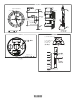
VERIFY ROTOR LOCATION
To ensure the rotor is properly located on the shaft: remove the back
cover if factory-preinstalled, and verify that the outer face of the rotor
is at the same depth as the alignment grooves, using a straight edge
tool. (Figure 3)
CAUTION
Do not use silicone sealants or caulk of any kind on
the motor or encoder face; these can cause
misalignment or sensor scraping damage. The XR67
electronics are fully sealed; water may enter and leave
the rotor area as needed. A drain hole option is available
if frequent moisture buildup is expected.
COVER INSTALLATION
Covers must not interfere with the motor shaft or rotor. The longest
shaft that can be used without interfering is 0.95” [25.1mm] with a
standard flat cover (Cover Style option “F”) and 2.80” [71.0mm] with
an extended “pie pan” cover (Cover Style option “E”). Through shaft
covers with seals are avail able for other applications (Cover Style
option “T”).
EXTENDED COVER MOUNT
(Cover Style option “E”)
The extended cover mounts to the encoder housing using quantity 4
#6-32 x 0.31” screws, lock washers, and thread locker.
THRU SHAFT AND FLAT COVER INSTALLATION
(Cover Style option “T” and “F”)
The housing has a machined step in the outboard face to accept the
cover and a recessed groove for the retaining ring. Insert the cover,
line up ears on cover, smooth side facing out, fully into the machined
step until it seats against shoulder. Using a spiral assembly method,
install the retaining ring by first inserting the squared off end into the
machined groove. Flex the ring and insert it into the groove walking
it around the perimeter (A flat blade screwdriver can be used). Final
position should have the ring fully seated into groove. Remove the
cover by reversing above procedure, starting with the tang end.
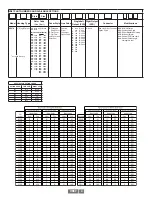
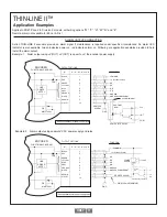
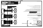
WIRING
Refer to the attached installation drawings referenced above for wiring
diagrams. Use the drawing appropriate for the encoder’s installation
location. Information on specific connector pin-outs and phasing can
be found on labels on the encoders and in the tables included in these
instructions.
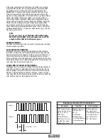
The XR67 can be wired for single phase or two phase, either with
or without complements, with or without markers. For bidirectional
operation, Phase A channel typically leads phase B channel for
clockwise shaft rotation as viewed from the anti-drive or accessory
end of the motor (XR67 mounting end). Refer to the pinout and
phasing tables for exceptions.
NOTE:
Wiring option “G” provides a pinout compatible with
Northstar
TM
encoders, with a cable shield connection
on pin 10. Note that this option does not ground the
shield.
CORRECTIVE ACTION FOR PHASE REVERSAL
1) Remove Power.
2) Exchange wires on cable, either at encoder cable end,
or at speed controller end (but not both).
a) Single Ended 2 Phase Wiring
(see wiring diagram)
Exchange A with B
b) Differential 2 Phase Wiring
(see wiring diagram)
Exchange either A with A– in the phase A pair OR
B with B– in the phase B pair but NOT both.
3) Apply Power.
4) Verify encoder feedback is correct, using hand rotation
of shaft, or jog mode of the speed controller.
Interconnecting cables specified in the Installation Drawings are
based on typical applications. Cable must be selected and installed
in accordance with regional standards. Physical properties of cable
such as abrasion, temperature, tensile strength, solvents, etc., are
dictated by the specific application. General electrical requirements
are: strand ed copper, 20 through 16 AWG (Industrial EPIC connector
type options can use 14 AWG), twisted wire pair overall shield ed with
braid or foil with drain wire, .05 uf of maximum total mutual or direct
capacitance, outer sheath insulator. See specifications for maximum
cable length. Strand ed 20 AWG wire should not be used for cable runs
great er then 61 meters. If 20 AWG is used with EPIC type connector
options the wire ends should be tinned.
FAULT-CHECK
After power-up and the rotor position is checked by the sensor, the
Fault-Check LED will turn green.
If the adaptive electronics reach their adjustment limit for any
reason, the Fault-Check alarm and LED will notify the drive and
operator of an impending failure. The LED will turn red if the
Adaptive Electronics reach their adjustment limit. This output occurs
before an actual failure, allowing steps to be taken to replace
the unit before it causes unscheduled downtime. Fault-Check
annunciation is available as an “alarm” output through the connector
(zone 2 and division 2 configurations only) and as an integral LED.
TROUBLESHOOTING
If the drive indicates a loss of encoder/tach fault and the XR67
fault-check LED is not illuminated, check the encoder power supply.
If power is present, check polarity; one indicator of reversed power
supply is that all outputs will be high at the same time. If the drive
indicates encoder fault, but the LED shows GREEN, then check the
wiring between the drive and the encoder. If the wiring appears
correct and in good shape, test the wiring by replacing the XR67.
If the new unit shows GREEN, and the drive still shows encoder
loss/tach fault, then the wiring is faulty and should be repaired or
replaced.
If the alarm output and/or LED indicate a fault (RED):
1. Remove the rear cover, and use the built-in gauge to check the
location of the rotor (see Figure 1). Ensure the label marked “This side
out” and/or cam screws is/are facing away from the motor.
2. Remove the XR67 from the motor. Clean the housing mounting
surface for the XR67 housing. Ensure the XR67 is directly mounted on
the motor, with no sealant, gasketing, or other materials, and is firmly
bolted in place.
Содержание Avtron SMARTSafe XR67
Страница 13: ...XR67 13...
Страница 14: ...XR67 14...


