Page 13
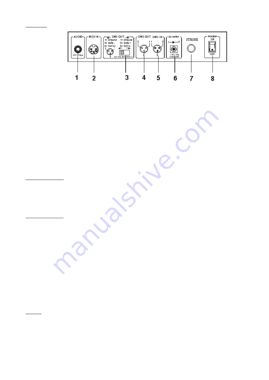
Rear View :
1. AUDIO IN –
0.1V~1Vp-p.
2. MIDI IN –
Receives MIDI data.
3. DMX Polarity Select –
Used to select DMX polarity.
4. DMX OUT –
This connector sends your DMX value to the DMX scanner or DMX pack.
5. DMX IN –
This connector accepts your DMX input signals.
6. DC Input –
DC9-12V, 500mA min..
8.
Strobe
This connector is used to control flash light.
8. Power Switch –
This switch turns On/Off the power.
OPERATION GUIDE
This unit allows you to program 12 scanners of 16 DMX channels, 30 banks of 8 programmable scenes, 6 chases of 240 programmed
scenes using 8 faders and other function buttons. With the use of two jog wheels, you may easily control the Pan or Tilt of the
scanners. To tailor your special effect lighting, this unit enables you to Assign or Reverse the DMX channels. In addition, two units can
set up communication so that they can send or receive file dump.
Display Information
The LCD Display contains a maximum of 2x8 characters.
LCD Display Message
CHASE 5
Chase 5 is activated.
STEP 002
The 2nd step of a chase
DATA 151
DMX value(000-255)
SP: 1M36S
The current Speed Time is 1 minute and 36 seconds
TP: 5.32S
The time of the last two taps is 5.32 seconds
FT: 10.5S
Fade Time is 10.5 seconds
ASS 07 08
Assign DMX channels 7 and 8
RES 10 13
Reverse DMX Channels 10 and 13
SN 6
Scene 6
BK 03
Bank 03
SET UP
Unit Setup
The unit is preset to allocate 16 channels per fixture. In order to assign your fixtures to the scanner buttons located on the
left side of the unit you will need to space your fixtures 16 DMX channels apart.
Use the Following chart for DMX Addressing


