• Do not connect devices which are not compliant with the specification.
• Every connected device should be compliant with the relevant safety standards.
• RGBW-Control and the load connected to its output must be powered by 12VDC or 24VDC stabilized power supply (SELV) with
short circuit protection. Connecting higher voltage or voltage not matching the load’s voltage may cause damage to the device.
• Connecting long RGBW/RGB/LED strips may cause voltage drops, resulting in lower light brightness further from R/G/B/W
outputs. To eliminate this effect it is recommended to connect few shorter strips in parallel connection instead of one long strip
connected serially.
• RGBW-Control has 0-10V inputs. There is no 0-10V output. Output is controlled by PWM at 244Hz.
• We recommend using momentary switches for comfortable light control.
• Field-installed conductors must be separated from uninsulated or bare live parts of a different circuit.
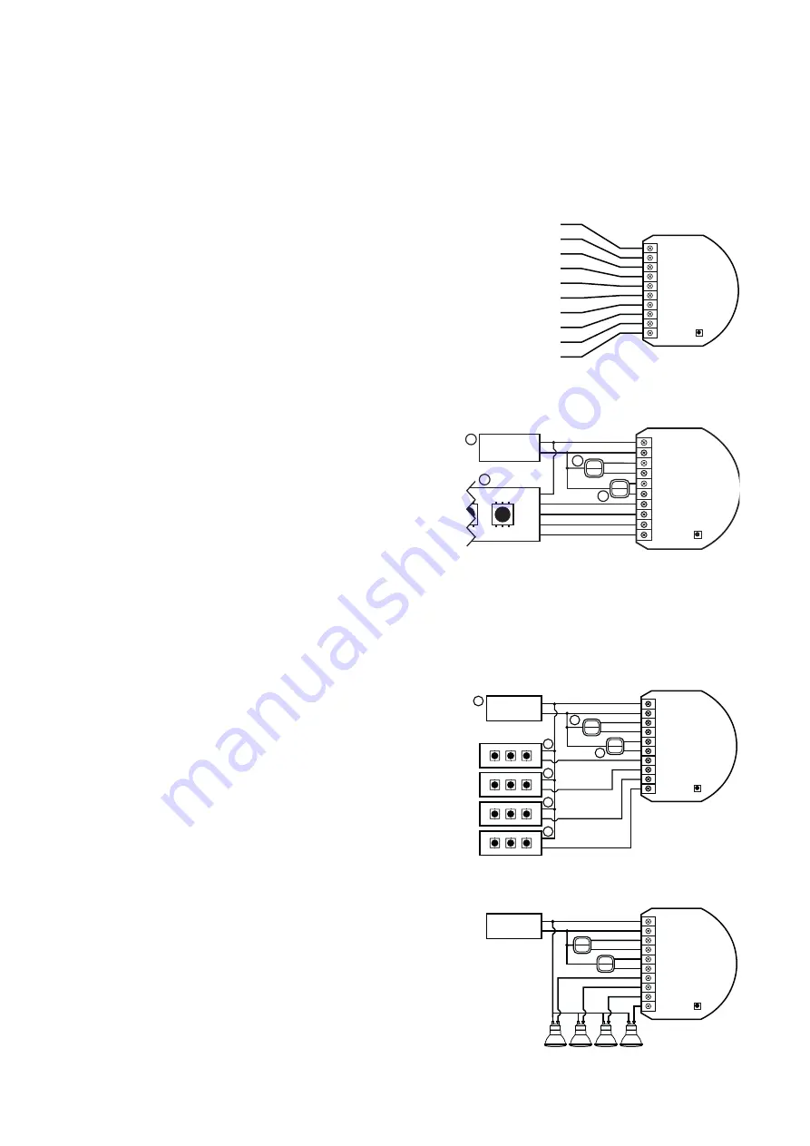
3.1 - Notes for the diagrams
P – 12/24V DC power supply connector
GND – ground connector
IN1 – input connector for controlling OUT1 output
IN2 – input connector for controlling OUT2 output
IN3 – input connector for controlling OUT3 output
IN4 – input connector for controlling OUT4 output
OUT1 – output connector controlled by IN1 input (red LED color recommended)
OUT2 – output connector controlled by IN2 input (green LED color recommended)
OUT3 – output connector controlled by IN3 input (blue LED color recommended)
OUT4 – output connector controlled by IN4 input (white LED color recommended)
B – service button (used to add/remove the device)
3.2 - Connection with RGBW/RGB LED strip
1. We recommend connecting LED strip channels in the same order as on the
diagram (R - OUT1, G - OUT2, B - OUT3, W - OUT4).
2. If you want to connect RGB strip, use the same diagram, but do not connect
OUT4 channel.
3. Disconnect the power.
4. Connect with the diagram on the right.
5. Verify correctness of connection.
6. Power the device.
7. Add the device to the Z-Wave network.
Note.
The device works in RGBW mode by default, to enable HSB mode change parameter 150 to 1.
IN3
IN4
R
G
B
W
P
GND
IN1
IN2
IN3
IN4
R
G
B
W
IN1
GND
P
IN2
B
3.3 - Connection with one-color LED strips
1. Disconnect the power.
2. Connect with the diagram on the right.
3. Verify correctness of connection.
4. Power the device.
5. Add the device to the Z-Wave network.
3.4 - Connection with halogen lights
1. Disconnect the power.
2. Connect with the diagram on the right.
3. Verify correctness of connection.
4. Power the device.
5. Add the device to the Z-Wave network.
12/24V DC
GND
IN3
IN4
OUT1
OUT2
OUT3
OUT4
IN1
GND
P
IN2
2
2
1
4
4
4
4
+
–
+
–
+
–
+
–
+
–
+
–
+
–
+
–
B
12/24V DC
GND
IN3
IN4
OUT1
OUT2
OUT3
OUT4
IN1
GND
P
IN2
12/24V DC
GND
12/24V
R
G
B
W
IN3
IN4
OUT1
OUT2
OUT3
OUT4
IN1
GND
P
IN2
2
2
1
3


