


• deceleration speed (0x44)
This parameter can be set with a value from 20% to 100%; the factory setting is 20%. This function enables you to program the speed of the motor while
learning the open and close positions and during the final phase of deceleration. Important – Always set this to the minimum speed required to operate the
door. Setting too high a speed can make it difficult to precisely determine the stop position.
Start up (0x8f)
The parameter can be set from 0 to 70V; the factory setting is 30V. The function sets the voltage at the start of a manoeuvre, to ensure sufficient torque at
low motor speeds. Important – This parameter must be set the value required for the motor to actually start the manoeuvre. Too high a setting can damage
the inverter and the motor by increasing the voltage too much.
Minimum frequency (0xac)
The parameter can be set from 2 to 7Hz; the factory setting is 2Hz. This sets the minimum start and stop frequency for the manoeuvre and, combined with
the start-up parameters, determines the automation's ability to start and stop moving the door. Important - Too high a setting can damage the inverter and
the motor by increasing the voltage too much.
Acceleration (0x5e)
This parameter can be set from 30 to 300rad/s2. The function sets the initial acceleration. Important - Too high a setting can damage the inverter and the
motor by increasing the voltage too much.
Deceleration (0x5f)
This parameter can be set from 30 to 300rad/s2. The function sets the deceleration. Important - Too high a setting can damage the inverter and the motor
by increasing the voltage too much.
Stop deceleration (0xae)
This parameter can be set from 50 to 500rad/s2. The function sets the emergency deceleration, when the door stops because of a safety device trip. Impor-
tant - Too high a setting can damage the inverter and the motor by increasing the voltage too much.
Motor heating (0x9e)
This parameter is of the ON / OFF type; the factory setting is “OFF”. When set to “ON”, it activates heating the motor when the ambient temperature is below
5°C.
Reserved 1 (0xaa)
This parameter accesses the inverter overcurrent controls. To modify this setting, contact Nice technical service.
Reserved 2 (0xab)
This parameter accesses the inverter protection equipment. To modify this setting, contact Nice technical service.
DIAGNOSTICS
Automation position
Indicates the physical position of the encoder in encoder pulses.
Inputs / Outputs
This function enables the display of the operating status of all inputs and outputs present on the control unit. The functions of the inputs and outputs are
described in Table 4.
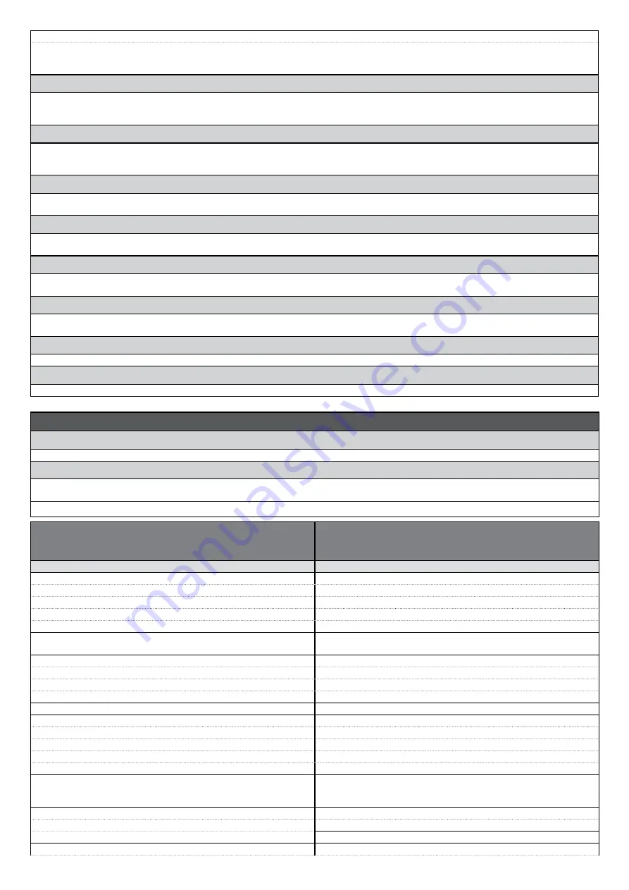
TABLE 4: Input/output DIAGNOSTICS
This function enables the display of the device type, operating
status, and configuration of the devices connected to the Bluebus
output.
DESCRIPTION
Diagnosis 1 - IN
RADIO INPUTS (On / Off):
Channel 1
Indicates when radio receiver channel 1 is active.
Channel 2
Indicates when radio receiver channel 2 is active.
Channel 3
Indicates when radio receiver channel 3 is active.
Channel 4
Indicates when radio receiver channel 4 is active.
SERIAL RADIO INPUTS
Indicates when the control unit receives a serial command via BusT4 from
a radio receiver; these commands range from minimum 1 to maximum 15.
BOARD KEYS:
no. 1
Indicates when key 1 is pressed (= OPEN) on the control unit.
no. 2
Indicates when key 2 is pressed (= STOP) on the control unit.
no. 3
Indicates when key 3 is pressed (= CLOSE) on the control unit.
DIRECTION SELECTION
Indicates the status of the direction selector for a manoeuvre.
INPUT STATUS:
inp 1
Indicates when input 1 is active.
inp 2
Indicates when input 2 is active.
inp 3
Indicates when input 3 is active.
inp alt
Indicates when the alt input is active.
ALT CONFIGURATION
Indicates the type of connection on the alt terminal. The connections are of
three types: not configured; NC; NO; 1 8K2 resistive edge; 2 8K2 resistive
edges; 1 OSE optical edge; out of range.
MOTOR 1 (On / Off):
Limit switch on opening
Indicates when motor 1 reaches the maximum opening position.
Limit switch on closing
Indicates when motor 1 reaches the maximum closing position.
MANOEUVRE THRESHOLD:
Indicates the operating status of the manoeuvre limiter, expressed in levels:


