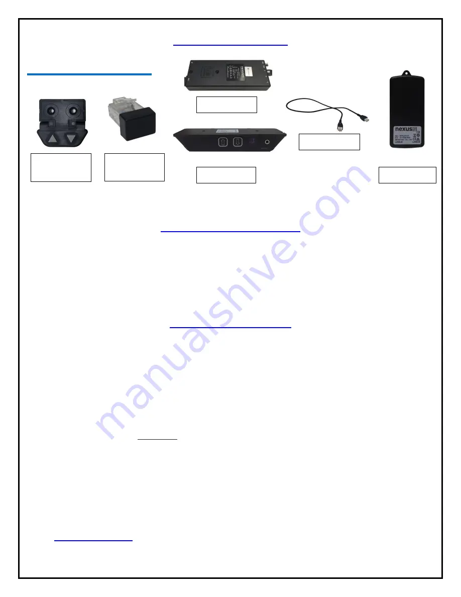
Nexus 21 L-75s Скачать руководство пользователя страница 31

31 
 

Reference Guide


Lift Components:


Setting your Height Limit 


Setting the Height Limit for IR and RF:


1.


Simply extend the lift to your desired height using 

IR Receiver

 or 

Wired Backup Switch

 and tap the down button 

to stop the lift at that height.  

2.


Then put the 

Height Limit Insert

 into either port A1 or A2 on the 

Control Box

3.


Your remote will now obey the height limit you have set. 


Common Procedures: 

Reinitialize: 

1.


Fully retract the lift;  

2.


Once the lift is fully retracted, press and hold the down button on either the 

Wired Backup Switch

 or 

IR 

Receiver

 for about 5-10 seconds. You should see a slight movement from the lift system.  

a.


Note:

 If you do not see the movement on the first attempt, release the down button and try these steps 

again. It may take 2 or 3 tries.  


Resetting the Lift from Safe Mode (Safe Mode occurs when power is lost while the lift is extended):


1.


The lift will only retract and it moves at half the speed. 

2.


Press and hold the down button until the lift fully retracts. 

3.


Then follow the steps to 

Reinitialize 

the lift. 


Pairing your RF Remote: 

1.


Locate the pinhole on the side of the 

RF Receiver


2.


Using a paper clip, press and hold the button inside the pin hole and the down button on the 

RF Remote

 at the 

same time. Keep them both held for 5 seconds.


a.


Note: 

The paper clip should only go a short distance into the 

RF Receiver

 to press the button. If your 

paper clip goes all the way in, reposition it and try again. 

3.


Release both buttons and try using your 

RF Remote

 again.


4.


If the remote does not respond, please contact our Technical Support at 480-275-8613 or email us at 

[email protected]

 for further troubleshooting.


Wired Backup 

Switch 

Height Limit 

Insert 

IR Receiver 

Interface Cable 

RF Receiver 

Control Box 

Motor Cable 

Содержание L-75s

Страница 1: ...1 TV Lift System Model L 75s Installation Instructions...

Страница 2: ...and installation please make sure that you have all items included on the list If any parts are missing or damaged please contact Nexus 21 Our contact information is shown at the top of this page Par...

Страница 3: ...e Screw 16 Twelve 12 6mm x 20mm Flat Head Machine Screw 17 Sixteen 16 6mm x 10mm Button Head Machine Screw 19 Eight 8 6mm x 12mm Button Head Machine Screw 20 Four 4 3 8 16 x Button Head Machine Screw...

Страница 4: ...ed 12 Keep all documentation 13 Heed all warnings 14 Clean only with a dry cloth 15 Refer all service questions to Nexus 21 if the system does not operate normally Nexus 21 disclaims any liability for...

Страница 5: ...r universal remote will learn the IR codes from the provided IR Handset which will enable you to control the lift The universal remote will then communicate with the eye located on the IR Receiver via...

Страница 6: ...of the Lift will be a minimum of 37 8 up to a maximum of 45 8 with the Top Support Brackets in the highest position See installation dimensions diagram on following page About the Cabinet Lid Cabinet...

Страница 7: ...y ii Lower Support Assembly iii Installing the Lift Columns into your Cabinet iv Upper Actuation Assembly a Assembling the Actuation System b Assembling the Cable Management System c Assembling the TV...

Страница 8: ...ew Small Hex Key Step 1 Attach 1 Base Plate to the Lower Lift Column using 2 6 x 10 mm BHMS screws Refer to picture 1 Step 2 Attached 1 Lower Column Supports to the Lower Lift Column using 2 6 x 10 BH...

Страница 9: ...lace the Lower Column Braces over the raised segments of the Rear Support Bracket to match picture 5 Step 6 Attach the 2 Lower Column Braces to the Rear Support Bracket using 8 6x 12 mm BHMS Screws Le...

Страница 10: ...acket Assembly 35 10 x THWS Screws Your Cabinet Phillips Drill Bit Drill Step 8 Place the Lower Support Bracket over the Lower Actuation System Ensure the Nexus 21 Logo is not upside down and the 90 d...

Страница 11: ...Columns Step 11 Center the Lift horizontally in your cabinet and mount the Lower Column Support and Base Plate for each column to the cabinet using 20 10 x THWS Screws Step 12 Repeat Step 10 if neces...

Страница 12: ...ex Key Step 13 Attach the Upper Lift Column to the Center Riser Bracket using 4 6 x 20 mm FHMS Screws Ensure that the pigtail cable for the Upper Lift Column is facing the interior of the Center Riser...

Страница 13: ...rt the Upper Actuation Assembly until you fasten it to the Lower Actuation Assembly See photo to the left for reference Step 17 Fasten the left side of the Upper Actuation Assembly to the Lower Actuat...

Страница 14: ...ter Plate and attach the Swivel Adapter Plate to the top of the Center Lift Column using 4 6 x 12 BHMS Screws Step 20 Re Attach the Swivel Mechanism to the Swivel Adapter Plate and fasten them togethe...

Страница 15: ...k Screen Support Actuation System 4 5 x 12 mm FHMS Screws 4 6 x 10 mm BHMS Screws 4 5m Motor Cable 6 Adapter Cable Small Hex Key 3 mm Hex Key Snakeskin Wrap Step 21 Attach the Cable Management Track t...

Страница 16: ...th the Swivel Cable and 4 5m Motor Cable up through the Right Cable Management Bracket through the Slot in the Center Riser Bracket and down through the Cable Management Track Step 25 Feed both the Sw...

Страница 17: ...racket with the threaded holes on the Swivel Mechanism and it using 4 6 x 10 BHMS Screws Step 27 Starting from the bottom of the Screen Support Bracket use the Snakeskin Wrap to wrap the Swivel Cable...

Страница 18: ...Cable Management Bracket to the right the pin the cables against the Center Riser Bracket and tighten the 2 6 x 20 FHMS Screws Step 29 Attach the right half of the Cable Management Track to the Rear S...

Страница 19: ...ck Plate using the 4 holes towards the middle of the Screen Support for now as adjustments will be covered in the Adjustments section of the Instruction Manual on page 28 Step 31 Using the remaining 2...

Страница 20: ...ing towards the front of the Lift System See photo to the left for reference Step 33 Attach both of the Top Plates to the top of the Top Support Brackets using 4 6 x 12 FHMS Screws Ensure that wings o...

Страница 21: ...ing the Lift System Step 34 Using the L 75s IR Wiring Diagram below connect the cables for your Lift System with IR Controls Note If you have RF Controls please see the next page for the L 75s RF Wiri...

Страница 22: ...22 Step 34 Continued Use this L 75s RF Wiring Diagram if you have RF Controls Note If you have IR Controls refer to the previous page...

Страница 23: ...with raised dot and a DOWN 3 Press the DOWN button and HOLD IT DOWN for approximately 5 seconds 4 You should see a slight movement in the Lift Column If you do not see the movement release the Down b...

Страница 24: ...TV 3 Using the four 4 Square Multi Mount washers and the TV mounting screws selected from the bag attach and tighten the hardware DO NOT OVERTIGTHEN HARDWARE DAMAGE TO TV MAY RESULT Diagram B install...

Страница 25: ...een Locks into both Vertical Mounting Bars Using 2 Screen Locks place one Screen Lock on the bottom set of hooks for each Vertical Mount Bar Using a Philips Head Screwdriver not provided tighten the S...

Страница 26: ...Plates are hand tight and centered before you mark your lid You may use the 2 outer holes or all 4 holes Step 42 Remove Cabinet Lid and drill two holes in the marked positions using a 7 32 drill bit d...

Страница 27: ...This option assumes that you have cut out part of your cabinet top customizing it to the size of your TV That cut out lid then sits on the Top Plate of the Lift System held in place by the Taper Pins...

Страница 28: ...pening This will provide a support point for the lid to rest on while the lift is in the fully retracted position assuring the lid is flush with the rest of the cabinetry every time There are multiple...

Страница 29: ...se all four bolt holes on the Screen Back Plate when adjusting the Top Support Brackets You can move the Screen Back Plate up and down along the Screen Support to raise and lower the position of the T...

Страница 30: ...30...

Страница 31: ...etting the Lift from Safe Mode Safe Mode occurs when power is lost while the lift is extended 1 The lift will only retract and it moves at half the speed 2 Press and hold the down button until the lif...

Страница 32: ...32 Connecting the Lift to your Home Control System...

Страница 33: ...33 Intentionally Left Blank...

Страница 34: ...34 Intentionally Left Blank...

Страница 35: ...35 Intentionally Left Blank...

Страница 36: ...36 866 500 5438...

Отзывы: