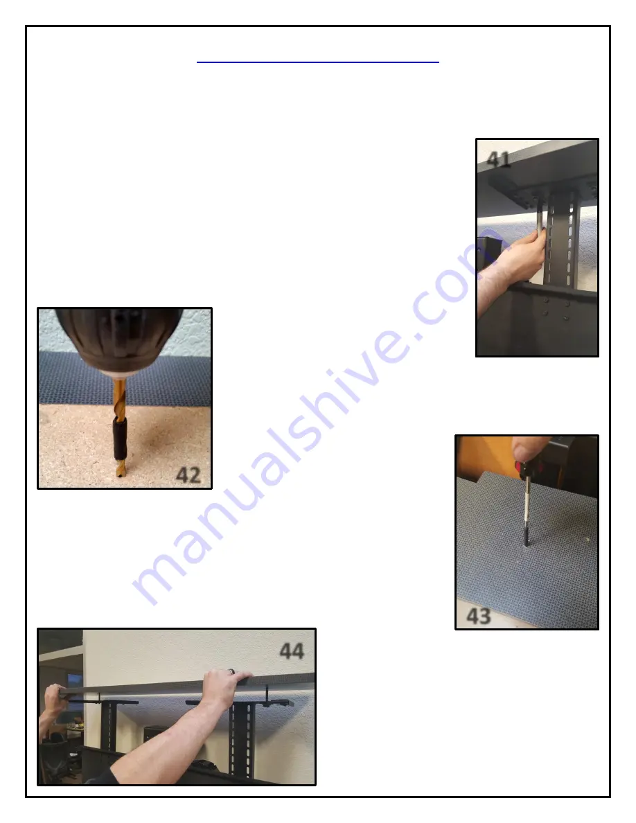
Nexus 21 L-75s Скачать руководство пользователя страница 26

26 
 

41 

42 

43 

44 

Attaching the Floating Lid


Step 39:

 Fully retract the lift and place the Cabinet Lid onto the Top Plates so that it is centered in the cabinet opening. 


Step 40:

 Run the Lift up using the IR or RF Controls and then back down. Make sure that when the lift comes down, the 

Cabinet Lid drops into a centered position within the cabinet opening.  

NOTE:

 You may temporarily tape your lid in place to prevent any shifting if needed. 


Step 41

: Run the lift all the way up, making sure the lid does not move out of place and 

locate “nesting holes” for each top plate. See photo to right for reference. Using a pencil or 
felt tipped pen, mark the position of each of the holes on the underside of the cabinet lid.


NOTE: 

Make sure the nuts on the bottom side of the Top Plates are hand tight and 

centered before you mark your lid. You may use the 2 outer holes or all 4 holes. 


Step 42:  

Remove Cabinet Lid and drill two holes in the marked positions


using a 

7/32” drill bit, ½” deep, in the underside of the Cabinet Lid.  


Tip: 

You can wrap tape around the bit, ½” deep to ensure you don’t go too far 

into the lid. 
 

Tip: 

If you have a granite, marble or quartz lid, 

you can put a wood sub decking below and then 
drill into that.


Step 43: 

Using a Phillips head screw


driver (not provided) screw each Tapered Pin into 

the holes drilled in step 16.


Step 44:

  Align the Tapered Pins with the holes you marked 

in Step 41 on the Top Plate and put the Lid on.  Tighten the 
nuts on the underside of the hole where the Tapered Pins 
pass through the Top Plate. 
 

NOTE:


The nests on the floating lid allow for up to 1/4" of 

tapered pin misalignment.  Before you tighten down the 
nests, make sure your lid aligns perfectly with the cabinet 
opening and floats freely for safety.


Содержание L-75s

Страница 1: ...1 TV Lift System Model L 75s Installation Instructions...

Страница 2: ...and installation please make sure that you have all items included on the list If any parts are missing or damaged please contact Nexus 21 Our contact information is shown at the top of this page Par...

Страница 3: ...e Screw 16 Twelve 12 6mm x 20mm Flat Head Machine Screw 17 Sixteen 16 6mm x 10mm Button Head Machine Screw 19 Eight 8 6mm x 12mm Button Head Machine Screw 20 Four 4 3 8 16 x Button Head Machine Screw...

Страница 4: ...ed 12 Keep all documentation 13 Heed all warnings 14 Clean only with a dry cloth 15 Refer all service questions to Nexus 21 if the system does not operate normally Nexus 21 disclaims any liability for...

Страница 5: ...r universal remote will learn the IR codes from the provided IR Handset which will enable you to control the lift The universal remote will then communicate with the eye located on the IR Receiver via...

Страница 6: ...of the Lift will be a minimum of 37 8 up to a maximum of 45 8 with the Top Support Brackets in the highest position See installation dimensions diagram on following page About the Cabinet Lid Cabinet...

Страница 7: ...y ii Lower Support Assembly iii Installing the Lift Columns into your Cabinet iv Upper Actuation Assembly a Assembling the Actuation System b Assembling the Cable Management System c Assembling the TV...

Страница 8: ...ew Small Hex Key Step 1 Attach 1 Base Plate to the Lower Lift Column using 2 6 x 10 mm BHMS screws Refer to picture 1 Step 2 Attached 1 Lower Column Supports to the Lower Lift Column using 2 6 x 10 BH...

Страница 9: ...lace the Lower Column Braces over the raised segments of the Rear Support Bracket to match picture 5 Step 6 Attach the 2 Lower Column Braces to the Rear Support Bracket using 8 6x 12 mm BHMS Screws Le...

Страница 10: ...acket Assembly 35 10 x THWS Screws Your Cabinet Phillips Drill Bit Drill Step 8 Place the Lower Support Bracket over the Lower Actuation System Ensure the Nexus 21 Logo is not upside down and the 90 d...

Страница 11: ...Columns Step 11 Center the Lift horizontally in your cabinet and mount the Lower Column Support and Base Plate for each column to the cabinet using 20 10 x THWS Screws Step 12 Repeat Step 10 if neces...

Страница 12: ...ex Key Step 13 Attach the Upper Lift Column to the Center Riser Bracket using 4 6 x 20 mm FHMS Screws Ensure that the pigtail cable for the Upper Lift Column is facing the interior of the Center Riser...

Страница 13: ...rt the Upper Actuation Assembly until you fasten it to the Lower Actuation Assembly See photo to the left for reference Step 17 Fasten the left side of the Upper Actuation Assembly to the Lower Actuat...

Страница 14: ...ter Plate and attach the Swivel Adapter Plate to the top of the Center Lift Column using 4 6 x 12 BHMS Screws Step 20 Re Attach the Swivel Mechanism to the Swivel Adapter Plate and fasten them togethe...

Страница 15: ...k Screen Support Actuation System 4 5 x 12 mm FHMS Screws 4 6 x 10 mm BHMS Screws 4 5m Motor Cable 6 Adapter Cable Small Hex Key 3 mm Hex Key Snakeskin Wrap Step 21 Attach the Cable Management Track t...

Страница 16: ...th the Swivel Cable and 4 5m Motor Cable up through the Right Cable Management Bracket through the Slot in the Center Riser Bracket and down through the Cable Management Track Step 25 Feed both the Sw...

Страница 17: ...racket with the threaded holes on the Swivel Mechanism and it using 4 6 x 10 BHMS Screws Step 27 Starting from the bottom of the Screen Support Bracket use the Snakeskin Wrap to wrap the Swivel Cable...

Страница 18: ...Cable Management Bracket to the right the pin the cables against the Center Riser Bracket and tighten the 2 6 x 20 FHMS Screws Step 29 Attach the right half of the Cable Management Track to the Rear S...

Страница 19: ...ck Plate using the 4 holes towards the middle of the Screen Support for now as adjustments will be covered in the Adjustments section of the Instruction Manual on page 28 Step 31 Using the remaining 2...

Страница 20: ...ing towards the front of the Lift System See photo to the left for reference Step 33 Attach both of the Top Plates to the top of the Top Support Brackets using 4 6 x 12 FHMS Screws Ensure that wings o...

Страница 21: ...ing the Lift System Step 34 Using the L 75s IR Wiring Diagram below connect the cables for your Lift System with IR Controls Note If you have RF Controls please see the next page for the L 75s RF Wiri...

Страница 22: ...22 Step 34 Continued Use this L 75s RF Wiring Diagram if you have RF Controls Note If you have IR Controls refer to the previous page...

Страница 23: ...with raised dot and a DOWN 3 Press the DOWN button and HOLD IT DOWN for approximately 5 seconds 4 You should see a slight movement in the Lift Column If you do not see the movement release the Down b...

Страница 24: ...TV 3 Using the four 4 Square Multi Mount washers and the TV mounting screws selected from the bag attach and tighten the hardware DO NOT OVERTIGTHEN HARDWARE DAMAGE TO TV MAY RESULT Diagram B install...

Страница 25: ...een Locks into both Vertical Mounting Bars Using 2 Screen Locks place one Screen Lock on the bottom set of hooks for each Vertical Mount Bar Using a Philips Head Screwdriver not provided tighten the S...

Страница 26: ...Plates are hand tight and centered before you mark your lid You may use the 2 outer holes or all 4 holes Step 42 Remove Cabinet Lid and drill two holes in the marked positions using a 7 32 drill bit d...

Страница 27: ...This option assumes that you have cut out part of your cabinet top customizing it to the size of your TV That cut out lid then sits on the Top Plate of the Lift System held in place by the Taper Pins...

Страница 28: ...pening This will provide a support point for the lid to rest on while the lift is in the fully retracted position assuring the lid is flush with the rest of the cabinetry every time There are multiple...

Страница 29: ...se all four bolt holes on the Screen Back Plate when adjusting the Top Support Brackets You can move the Screen Back Plate up and down along the Screen Support to raise and lower the position of the T...

Страница 30: ...30...

Страница 31: ...etting the Lift from Safe Mode Safe Mode occurs when power is lost while the lift is extended 1 The lift will only retract and it moves at half the speed 2 Press and hold the down button until the lif...

Страница 32: ...32 Connecting the Lift to your Home Control System...

Страница 33: ...33 Intentionally Left Blank...

Страница 34: ...34 Intentionally Left Blank...

Страница 35: ...35 Intentionally Left Blank...

Страница 36: ...36 866 500 5438...

Отзывы: