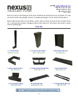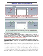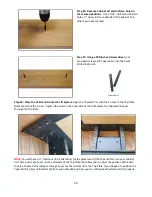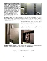
13
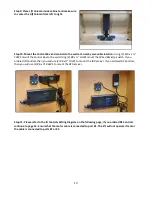
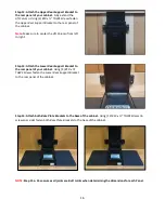
Step 9: Place
Lift Column
inside cabinet and make sure
to center the
Lift Column
from left to right.
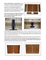
Step 10: Mount the
Control Box
and controls to the wall at a nearby accessible location:
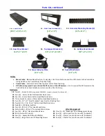
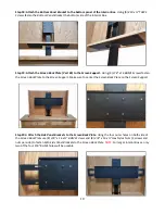
Using (2)
#10 x 1 ¾”
FHWS
mount the
Control Box
to the wall. Using (2)
#8 x ¾” FHWS
mount the
Wired Back Up Switch
. If you
ordered
IR Controls
, then you will use (2)
#8 x ¾” FHWS
to mount the
IR Receiver
. If you ordered
RF Controls
,
then you will use (2)
#6 x ¾” RHWS
to mount the
RF Receiver.
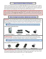
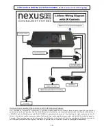
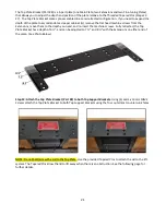
Step 11: Please refer to the IR Controls Wiring Diagram on the following page, if you ordered RF Controls
continue to page 14. Ensure that the motor cable is connected to port #1. The lift will not operate if motor
the cable is connected to ports #2 or #3.
Содержание L-45ens
Страница 1: ...TV Lift System Model L 45ens Installation Instructions ...
Страница 2: ...2 ...
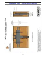
Страница 27: ...27 Supplemental Page A L 45ens Installation Dimensions ...
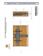
Страница 28: ...28 Supplemental Page A L 45ens Installation Dimensions Page 2 ...
Страница 30: ...30 Supplemental Page C Connect the Lift to Home Control System ...
Страница 31: ...31 ...
Страница 32: ...32 866 500 5438 ...


