


PSH150
user manual rev4
Page 4/15
1 Product description
Use latest device Documentation, Software and Firmware to ensure reliable operation of
the system (downloadable from www.nextys.com).
PSH150 is an advanced DIN rail 1-phase input, 150W SMPS (Switched Mode Power Supply) with a
distinctive feature:
10kV isolation between primary and secondary
.
This allows it to be used in energy management, telecom, renewable energy and other demanding
applications.
Figure 1: Front panel view
1. AC input
: 2 poles are provided for input connection. This must be connected to the AC or
DC line source. V
oltage range is 90…277Vac or 110…400Vdc.
2. Modbus over USB
: Used to connect a device running
POWERMASTER
or custom
application. Firmware update is also possible.
3. Modbus over RS-485
: Used to connect a device running
POWERMASTER
or custom
application. Firmware update is also possible.
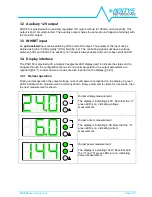
4. INHIBIT input
: A voltage between 5Vdc and 30Vdc applied to this input activates the
inhibit function (§3.3).
5. Auxiliary 12Vdc output
: This output provides a regulated 12Vdc output with 100mA
maximum output current. This output is short circuit protected (§3.2).
6. DC-OK dry contact
: normally open and normally closed relay contacts are available; the
relay closes when the output voltage is >90% of the programmed output voltage value.
7. DC Output
: 4 poles are provided for output connection; it must be connected to the load.
The output voltage is adjustable between 5…55Vdc. (§3.1)
8. Control keys
: 3 push buttons are provided to navigate through menus and to select
various functions.
9. Display
: 3-digits LED display providing information about the device status (§3.4).
10. Units LEDs
: 2 green LEDs are used to indicate the actual measurement indicated on the
display (§3.4.1).
11. Alarm LED
: blinking when there is an alarm; the relevant alarm code is indicated on the
display (§3.4.3).