


6. Quick test
In order to test if the X-Dot I/O is installed correctly, please follow the test procedure below:
© 2022 Nexmosphere. All rights reserved. v1.0 / 08-28
All content contained herein is subject to change without prior notice
N ex m o s p h e re
Le H av re 1 3 6
5 6 2 7 SW E i n d h ove n • T h e N e t h e r l a n d s
T
+ 3 1 4 0 2 4 0 7 0 7 0
E
s u p p o r t @ n ex m o s p h e re.c o m
PRODUCT MANUAL | X-DOT I/O INTERFACE
7
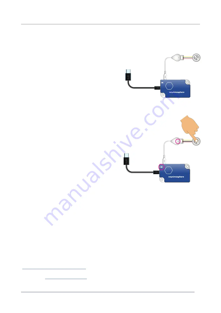
Step 1 - Setup
First, connect an Input device such as a push button
to the X-Dot I/O. Secondly, connect the X-Dot I/O to
an Xperience controller and power the Xperience
controller.
The green status LED of the X-Dot I/O should go on.
The status LED of the controller will start to blink and
once power-up is completed will be lit continuously
Step 2 - Test
Activate the Input device (e.g. push the button)
Both the green status LED of the sensor and the status
LED of the controller should blink.
For a full test we recommend to connect the setup to
a mediaplayer or PC and test all API commands listed
in this document (see section 3, page 2-3). For more
information on how to setup a test for your controller,
please see the Quick Start Guide of the Xperience
controller you are using. These are available on
nexmosphere.com/support-documentation
Please contact
for any
support questions you may have.
In case any of the steps above does not provide
the expected result, please check the installation
guidelines in this document.
XN
Connect to powered
USB port
XN
LED BLINK
LED BLINK


