


© 2022 Nexmosphere. All rights reserved. v1.0 / 08-28
All content contained herein is subject to change without prior notice
N ex m o s p h e re
Le H av re 1 3 6
5 6 2 7 SW E i n d h ove n • T h e N e t h e r l a n d s
T
+ 3 1 4 0 2 4 0 7 0 7 0
E
s u p p o r t @ n ex m o s p h e re.c o m
3
PRODUCT MANUAL | X-DOT I/O INTERFACE
Example commands
Set button LED on
Set button LED off
M
= Mode
SS
= Brightness Start value
EE
= Brightness End value
DD
= Duration
1
=on,
2
=off,
3
=single ramp,
4
=pulse continuous
value between
00-99
(% brightness)
value between
00-99
(% brightness)
value between
00-99
(in 0.1 seconds)
Ramp from 00% brightness to 99% brightness in 1.2s
Ramp from 80% brightness to 20% brightness in 0.7s
Continuously pulse from 00% to 99% brightness in 1.0s
Continuously pulse from 10% to 50% brightness in 0.5s
4 - Installation requirements and guidelines
When integrating an X-Dot I/O into your digital signage installation, several installation requirements and guidelines need to
be taken into account in order for the sensor to perform optimal and operate stable.
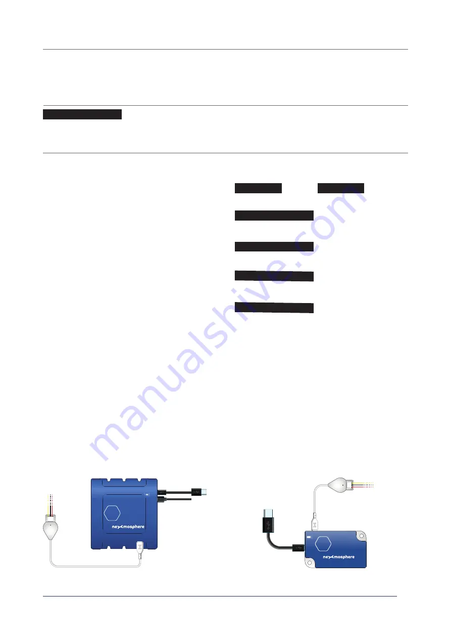
4.2 Connection Diagrams
The X-Dot I/O can be connected to any X-talk interface and is therefore compatible with all Xperience controllers. Make sure
the X-Dot I/O is connected to the X-talk interface before powering the Xperience controller. Otherwise, the X-Dot I/O will not
be recognized by the Xperience controller and no output will be provided.
4.1 Electrical installation requirements
The maximum amount of power which the Output pin can provide is 200mA. In case of connecting 3rd party output devices,
please make sure the specifi cations comply.
Example connection to XC Controller
Example connection to XN Controller
3.3 - Control button LEDs
A button LED is an Output device and can be set ON or OFF via the method explained on the previous page. Additionally, the
X-Dot I/O can control the button LED with a PWM signal on the Output pin, off ering the option to smoothly dim the LED up
and down and create pulsing patterns. This can be done by sending the following API command:
X001B[
MSSEEDD
]
X001B[3009912]
X001B[1]
X001B[2]
X001B[3802007]
X001B[4009910]
X001B[4105005]
When controlling button LEDs with a PWM signal, consider
the following:
•
When Mode is set to 1 (On) or 2 (Off ), all other
parameters are irrelevant and therefore ignored.
• When Mode is set to 3 (Single ramp), the button LED
will transition 1x from the Start value to the End value
in the indicated Duration time.
• When Mode is set to 4 (Pulse), the button LED will
continuously transition back-forth between the Start
value and the End value in the indicated Duration time.
• When sending a Mode 3 or 4 command, the Output
pin will immediatly be set to the Start value. There is
no fade transition between the current state of the
Output pin and the Start value.
DC Power supply
XC
XN


