20
Model 8703 System
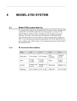
4.1.4
Power Input
Supply power to the Model 8703 via the 2-pin connector, J100. Connect Pin
1 to the power source ground, and connect Pin 2 to the +10 V to +12 V power
source. Diode D107 and D108 protect the Model 8703 against reversed
power wiring.
4.1.5
Analog Control
Connector J101 provides interface for control and monitor signals. Pins 1 and
2 are inputs for the analog voltage used to set the pulse rate. These inputs are
only used when the DIP switches at S100 are set for LINEAR (off on) or
BANG-BANG (off off). Connect ANALOG IN+ to a positive voltage and
connect ANALOG IN- to the analog ground associated with the ANALOG
IN+ voltage source: reverse the polarity to change the direction of the
Picomotor. D100 and D101 are bipolar TVS diodes that shunt voltage spikes
to GROUND. D100 and D101 are most useful when long wires are used to
connect Pins 1 and 2 to the pulse-rate-controlling voltage source.
4.1.6
Digital Control
Pin 3 is the return line for the DIR/A, PULSE/B, LIDLE, and LFAULT opto-
isolators. Connect it to the logic ground for the source of these signals
(destination for LFAULT). Pin 3 can be connected to terminal 1 GROUND if
a simple set-up is needed. DIR/A, PULSE/B, LIDLE, and LFAULT will
function only if terminal 6 is connected to the proper ground.
Pins 4 and 5 are used for step and direction input when the DIP switches are
set for DIR/PULSE (on on) or QUAD (on off). See the data sheet for a
detailed discussion of the digital control modes. R100 and R101 limit the
current flow through the opto-isolator inputs. If 5V logic (TTL) drives Pins 4
and 5, the current-limiting resistors in the Model 8703 are sufficient. R100
and R101 should be increased if higher voltage logic is used. For example,
suppose you want to use 12V logic:
The 8712’s internal 470
Ω
0603-package resistor’s maximum
dissipation=0.063 W.
The opto-isolator diode drop=1.4 V.
You should calculate R such that the internal resistor dissipation is 50% of
maximum, at 0.032W.
mA
2
.
8
470
W
032
.
0
I
Current
=
Ω
=
Ω
=
⋅
Ω
−
−
=
822
mA
2
.
8
mA
2
.
8
470
V
4
.
1
V
12
R
Rounding to the nearest 10% standard resistor value results in a value of
R=820
Ω
.
820
Ω
x (8.2 mA2) = 0.055 W, so the 0603 package is marginal and you
should use 0805.
Содержание New Focus 8703
Страница 1: ...Model 8712 Picomotor Driver Model 8703 System Driver User s Manual Single Axis Picomotor Driver ...
Страница 10: ......
Страница 34: ...24 Model 8703 System 4 3 Model 8703 System Board Layout System Board Upper Layer Top View ...
Страница 35: ...Model 8703 System 25 System Board Bottom Layer Top View Dimensions of Model 8703 ...


