10
Theory of Operation
When LIDLE is pulled low, the microprocessor shuts down the power supply
and stops generating Picomotor drive pulses. The response to this input is
rapid enough to prevent the generation of more than one pico pulse after
LIDLE goes low. Normal operation resumes after LIDLE is brought high.
3.2
Input Mode Control Bits
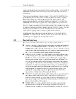
MODE0 and MODE1 are decoded when the power is applied. The interface
mode can only be changed by removing power to the 8712, then changing the
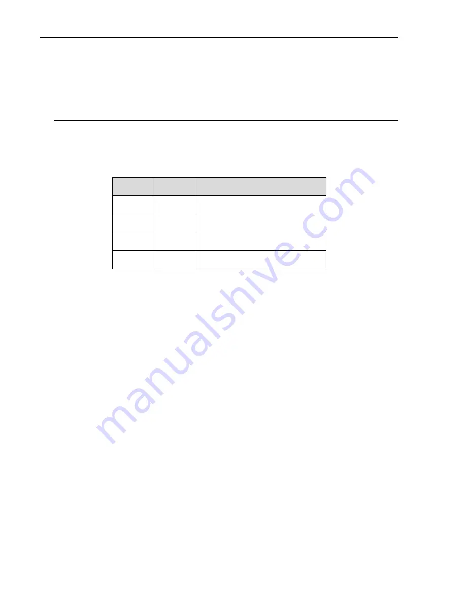
mode bits and applying power again. MODE0 and MODE1 define the control
interface as follows:
3.2.1
Step/Direction Mode
In this mode, DIR+/A is the direction input. PULSE+/B is the pulse
command input. TTL inputs to the control interface determine pulse
generation and the direction of motion. One Picomotor pulse is generated for
each falling edge of PULSE+/B. PULSE+/B can be left in either a high or
low state because it is edge sensitive. The low state is preferred because the
opto-coupler input diode will be off.
DIR+/A causes clockwise motion when high, and counter-clockwise motion
when low. It is checked before each pulse is made to allow instantaneous
direction reversal. DIR+/A is level sensitive, so it must be in the desired state
when PULSE+/B goes low and remain in that state for a minimum of
100 μs
after PULSE+/B goes low. The pulse rate can be between 0 and 2 kHz. Faster
pulse rates will not result in increased response.
3.2.2
Quadrature Mode
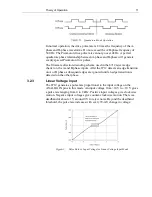
In this mode, DIR+/A is the A-phase input and the PULSE+/B is the B-phase
input. Like the step/direction mode, quadrature mode uses the digital control
interface. In this mode a pulse is generated for every edge transition of both
the A-phase and B-phase control inputs. The direction of motion is
determined by the phase of A with respect to B:
MODE0
MODE1
Description
0
0
Step/Direction Mode
1
0
Quadrature Mode
0
1
Line Voltage Input
1
1
Bang-Bang Voltage Input
Содержание New Focus 8703
Страница 1: ...Model 8712 Picomotor Driver Model 8703 System Driver User s Manual Single Axis Picomotor Driver ...
Страница 10: ......
Страница 34: ...24 Model 8703 System 4 3 Model 8703 System Board Layout System Board Upper Layer Top View ...
Страница 35: ...Model 8703 System 25 System Board Bottom Layer Top View Dimensions of Model 8703 ...


