Theory of Operation
11
Quadrature-Mode Operation
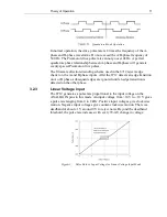
In normal operation, the drive pulse rate is 4 times the frequency of the A-
phase and B-phase waveforms. Do not exceed the A/B-phase frequency of
500 Hz. The Picomotor drive pulse rate cannot go over 2kHz. A perfect
quadrature phase relationship between A-phase and B-phase will generate
evenly spaced Picomotor drive pulses.
The firmware direction-decoding scheme used in the 8712 rejects edge
chatter on the A and B phase inputs. After the 8712 detects an edge transition
on A or B phase, subsequent edges are ignored until an edge transition is
detected on the other phase.
3.2.3
Linear Voltage Input
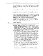
The 8712 generates a pulse rate proportional to the input voltage on the
ANALOG IN pins in this mode. An input voltage from +10 V to –10 V gives
a pulse rate ranging from 0 to 2 kHz. Positive input voltages give clockwise
motion. Negative input voltages give counter-clockwise motion. There is a
deadband of about ±1 V around 0 V to reject noise. Beyond the deadband
threshold, the pulse rate increases with every 78-mV change in voltage:
Pulse Rate vs. Input Voltage for Linear Voltage Input Mode
Содержание New Focus 8703
Страница 1: ...Model 8712 Picomotor Driver Model 8703 System Driver User s Manual Single Axis Picomotor Driver ...
Страница 10: ......
Страница 34: ...24 Model 8703 System 4 3 Model 8703 System Board Layout System Board Upper Layer Top View ...
Страница 35: ...Model 8703 System 25 System Board Bottom Layer Top View Dimensions of Model 8703 ...


