12
Theory of Operation
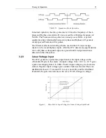
Detailed View of Pulse Rate vs. Input Voltage around the dead-band for
Linear
Voltage
Input Mode
Voltages between 78-mV steps will cause the pulse frequency to switch back
and forth between two pulse frequencies. Connect ANALOG IN+ to a low
impedance voltage source. Connect ANALOG IN- to the analog signal
ground associated with the source of ANALOG IN+. Ground loop noise can
be introduced into the analog inputs when SYSTEM GROUND is used
instead of analog signal ground. Reverse the ANALOG IN connections to
change the polarity sense of the analog input voltage.
3.2.4
Bang-Bang Voltage Input
In this analog input mode, a voltage exceeding the deadband threshold gives
the maximum 2 kHz pulse rate. Positive input voltages give clockwise
motion. Negative input voltages give counterclockwise motion. This mode
should not be used continuously without forced air cooling of the 8712 at
ambient temperatures higher than 25 °C. The unit has a temperature time
constant of 6 minutes. Operation in Bang-Bang mode is acceptable for less
than 50% duty cycle and less than 3 minutes of continuous operation in still
air at 55 °C.
For heatsink mounting and recommended parts refer to section 3.4.1 and
Figure 14.
3.3
Status Indicators
The red and green LED indicators are visible inside the module’s casing
through small holes. They provide a visual indication of the unit’s status.
Содержание New Focus 8703
Страница 1: ...Model 8712 Picomotor Driver Model 8703 System Driver User s Manual Single Axis Picomotor Driver ...
Страница 10: ......
Страница 34: ...24 Model 8703 System 4 3 Model 8703 System Board Layout System Board Upper Layer Top View ...
Страница 35: ...Model 8703 System 25 System Board Bottom Layer Top View Dimensions of Model 8703 ...


