


Section 41 - Steering - Chapter 2
41-2-4
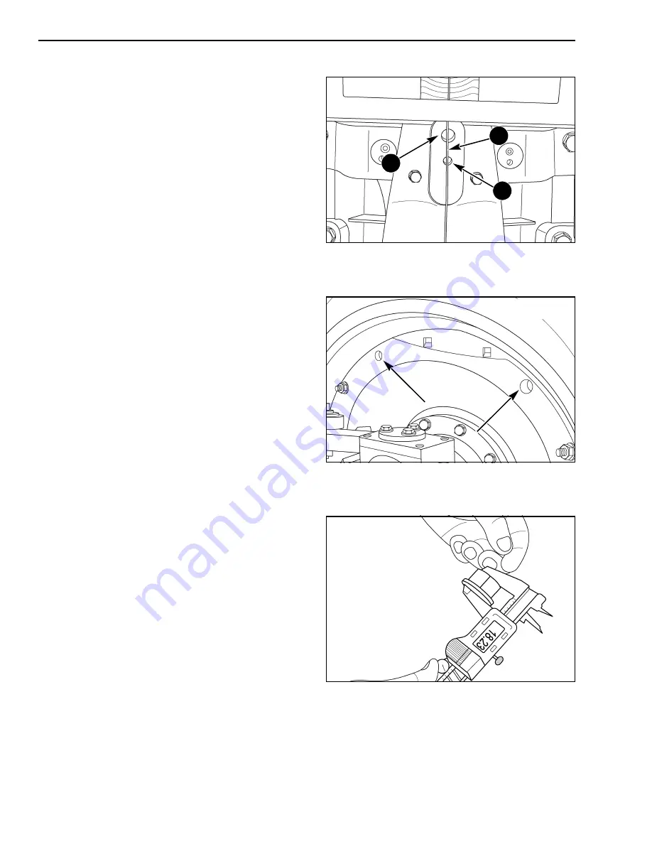
STEP 4
Steer the axle until the string (1) hangs vertically and
bisects the dowel hole (2) and threaded hole (3) in
the drag link. The axle will then be “Dead Centered”.
NOTE: The string must hang freely between the
drag link and weight support bracket.
NOTE: If this step is not performed correctly, all
other measurements and adjustments will be
incorrect.
STEP 5
Remove two nuts and washers from the rim mounting
bolts from the location shown. Use an appropriate
solvent to clean the nuts and washers.
STEP 6
Measure the combined thickness of the nut and
washer. The stack height must be within 0.05 mm
(0.002 in.) of each other. If they are not within
specification, obtain new hardware and ver ify
combined thickness.
RD05E080
3
2
1
RD05E081
RD05E082
Содержание T8010
Страница 22: ...Section 00 Chapter 1 January 2006 STANDARD TORQUE SPECIFICATION ...
Страница 28: ...Section 00 Chapter 2 January 2006 SAFETY GENERALINFORMATION MAINTENANCE SCHEDULE ...
Страница 35: ...Section 00 General Information Chapter 2 00 2 8 This Page Left Blank ...
Страница 36: ...Section 10 Chapter 1 January 2006 ENGINE REMOVAL AND INSTALLATION ...
Страница 37: ...Section 10 Engine Chapter 1 10 1 2 TABLE OF CONTENTS ENGINE REMOVAL 10 1 3 ENGINE INSTALLATION 10 1 10 ...
Страница 52: ...Section 10 Chapter 2 January 2006 FUEL TANK FUEL SENDER REMOVAL AND INSTALLATION ...
Страница 63: ...Section 10 Engine Chapter 2 10 2 12 ...
Страница 64: ...Section 10 Chapter 3 January 2006 HOOD REMOVAL INSTALLATION ...
Страница 65: ...Section 10 Engine Chapter 3 10 3 2 TABLE OF CONTENTS HOOD REMOVAL 10 3 3 HOOD INSTALLATION 10 3 5 ...
Страница 70: ...Section 10 Chapter 4 January 2006 COOLING SYSTEM MODULE REMOVAL AND INSTALLATION ...
Страница 80: ...Section 10 Chapter 5 January 2006 VISCOUS FAN DRIVE TEST ...
Страница 90: ...Section 21 Chapter 1 January 2006 POWERSHIFT TRANSMISSION SYSTEM How It Works and Troubleshooting ...
Страница 140: ...Section 21 Chapter 2 January 2006 FRONT FRAME TO SPEED TRANSMISSION SPLIT ...
Страница 151: ...Section 21 Transmission Drivelines Chapter 2 21 2 12 This Page Left Blank ...
Страница 152: ...Section 21 Chapter 3 January 2006 SPEED TO RANGE TRANSMISSION SPLIT ...
Страница 161: ...Section 21 Transmission Drivelines Chapter 3 10 This Page Left Blank ...
Страница 162: ...Section 21 Chapter 4 January 2006 SPEED TRANSMISSION ...
Страница 244: ...Section 21 Chapter 5 January 2006 RANGE TRANSMISSION TO REAR FRAME SPLIT ...
Страница 254: ...Section 21 Chapter 6 January 2006 RANGE TRANSMISSION ...
Страница 330: ...Section 21 Chapter 7 January 2006 TRANSMISSION CONTROL VALVES AND INCHING VALVE ...
Страница 351: ...Section 21 Transmission Drivelines Chapter 7 21 7 22 This Page Left Blank ...
Страница 352: ...Section 21 Chapter 8 January 2006 REAR FRAME ...
Страница 392: ...Section 21 Chapter 9 January 2006 HYDRAULIC PUMP DRIVE ...
Страница 404: ...Section 25 Chapter 1 January 2006 FRONT WHEEL DRIVE FWD CONTROL SYSTEM How It Works ...
Страница 407: ...Section 25 Four Wheel Drive Front Axle Chapter 1 25 1 4 RI02E086 1 FWD SOLENOID 2 POWERSHIFT VALVE RANGE 1 2 ...
Страница 409: ...Section 25 Four Wheel Drive Front Axle Chapter 1 25 1 6 RH05J060 1 FRONT WHEEL DRIVE FWD SWITCH 1 ...
Страница 416: ...Section 25 Chapter 2 January 2006 DIFFERENTIAL LOCK CONTROL SYSTEM How It Works ...
Страница 419: ...Section 25 Four Wheel Drive Front Axle Chapter 2 25 2 4 RI02E086 1 PTO DIFF LOCK VALVE 2 DIFF LOCK CLUTCH SOLENOID 1 2 ...
Страница 421: ...Section 25 Four Wheel Drive Front Axle Chapter 2 25 2 6 RD05J060 1 DIFFERENTIAL LOCK SWITCH 1 ...
Страница 431: ...Section 25 Four Wheel Drive Front Axle Chapter 2 25 2 16 This Page Left Blank ...
Страница 432: ...Section 25 Chapter 3 January 2006 FWD OUTPUT SHAFT ...
Страница 447: ...Section 25 Four Wheel Drive Front Axle Chapter 3 25 3 16 This Page Left Blank ...
Страница 448: ...Section 25 Chapter 4 January 2006 FWD DRIVE SHAFT ...
Страница 449: ...Section 25 Four Wheel Drive Front Axle Chapter 4 25 4 2 TABLE OF CONTENTS SPECIAL TORQUES 25 4 3 FWD DRIVE SHAFT 25 4 4 ...
Страница 455: ...Section 25 Four Wheel Drive Front Axle Chapter 4 25 4 8 ...
Страница 456: ...Section 25 Chapter 5 January 2006 SUSPENDED FWD AXLE SYSTEM How It Works and Troubleshooting ...
Страница 474: ...Section 25 Chapter 6 January 2006 SUSPENDED FWD AXLE REMOVAL ...
Страница 480: ...Section 25 Chapter 7 January 2006 SUPERSTEER AXLE REMOVAL AND INSTALLATION ...
Страница 489: ...Section 25 Four Wheel Drive Front Axle Chapter 7 25 7 10 ...
Страница 490: ...Section 25 Chapter 8 January 2006 LIMITED SLIP FWD DIFFERENTIAL ...
Страница 517: ...Section 25 Four Wheel Drive Front Axle Chapter 8 25 8 28 ...
Страница 518: ...Section 25 Chapter 9 January 2006 LOCKING FWD DIFFERENTIAL ...
Страница 546: ...Section 25 Chapter 10 January 2006 FWD PLANETARY HUB STEERING KNUCKLE AND AXLE DRIVE SHAFT ...
Страница 588: ...Section 25 Chapter 11 January 2006 SUSPENSION FWD AXLE ...
Страница 613: ...Section 25 Four Wheel Drive Front Axle Chapter 11 25 11 26 ...
Страница 614: ...Section 25 Chapter 12 January 2006 SUPERSTEER AXLE VERTICAL CONTROL LINKAGE ...
Страница 620: ...Section 27 Chapter 1 January 2006 REAR AXLE AND PLANETARIES ...
Страница 652: ...Section 31 Chapter 1 January 2006 POWER TAKE OFF CONTROL SYSTEM How it Works ...
Страница 656: ...Section 31 PTO Chapter 1 31 1 5 RD05J060 1 PTO CONTROL SWITCH 1 ...
Страница 670: ...Section 31 Chapter 2 January 2006 PTO CLUTCH ASSEMBLY Single Reversible and Dual Speed ...
Страница 684: ...Section 31 PTO Chapter 2 31 2 15 STEP 42 Remove bearing cones from each side of the bearing cage RD05D008 RD05D010 ...
Страница 715: ...Section 31 PTO Chapter 2 31 2 46 This Page Left Blank ...
Страница 716: ...Section 33 Chapter 1 January 2006 BRAKE VALVE ...
Страница 724: ...Section 33 Brakes Chapter 1 33 1 9 STEP 26 102RS5 Install the right side cover ...
Страница 725: ...Section 33 Brakes Chapter 1 33 1 10 ...
Страница 726: ...Section 33 Chapter 2 January 2006 BRAKE CYLINDERS ...
Страница 735: ...Section 33 Brakes Chapter 2 33 2 10 ...
Страница 738: ...Section 35 Chapter 1 January 2006 HOW TO READ SYMBOLS IN A HYDRAULIC SCHEMATIC ...
Страница 749: ...Section 35 Hydraulic Systems 3PT Chapter 1 35 1 12 NOTES ...
Страница 757: ...Section 35 Hydraulic Systems 3PT Chapter 1 35 1 20 ...
Страница 758: ...Section 35 Chapter 2 January 2006 HYDRAULIC SYSTEM HOW IT WORKS WITH TROUBLESHOOTING ...
Страница 807: ...Section 35 Hydraulic Systems 3PT Chapter 2 35 2 50 This Page Left Blank ...
Страница 808: ...Section 35 Chapter 3 January 2006 PTO AND DIFFERENTIAL LOCK VALVE ...
Страница 818: ...Section 35 Chapter 4 January 2006 REMOTE VALVE AND COUPLER SERVICE ...
Страница 832: ...Section 35 Chapter 5 January 2006 REMOTE HYDRAULIC SYSTEM How It Works and Troubleshooting ...
Страница 866: ...Section 35 Chapter 6 January 2006 PRIORITY AND REGULATOR VALVE ...
Страница 880: ...Section 35 Chapter 7 January 2006 CHARGE PUMP ...
Страница 884: ...Section 35 Chapter 8 January 2006 PFC PISTON PUMP ...
Страница 888: ...Section 35 Chapter 9 January 2006 HITCH SYSTEM How it Works ...
Страница 910: ...Section 35 Chapter 10 January 2006 HITCH CONTROL VALVE ...
Страница 921: ...Section 35 Hydraulic Systems 3PT Chapter 10 35 10 12 ...
Страница 922: ...Section 35 Chapter 11 January 2006 TRACTOR HITCH ...
Страница 949: ...Section 35 Hydraulic Systems 3PT Chapter 11 35 11 28 This Page Left Blank ...
Страница 950: ...Section 41 Chapter 1 January 2006 STEERING COLUMN AND STEERING HAND PUMP REMOVAL AND INSTALLATION ...
Страница 961: ...Section 41 Steering Chapter 1 41 1 12 ...
Страница 962: ...Section 41 Chapter 2 January 2006 WHEEL TOE IN SETTING SuperSteer FWD Axle ...
Страница 972: ...Section 50 Chapter 1 January 2006 AIR CONDITIONING SYSTEM Troubleshooting and Fault Codes ...
Страница 1061: ...Section 50 Climate Control Chapter 1 50 1 90 NOTES ...
Страница 1062: ...Section 50 Chapter 2 January 2006 AIR CONDITIONER SYSTEM SERVICE ...
Страница 1182: ...Section 55 Chapter 1 January 2006 ELECTRICAL SYSTEM How It Works And Troubleshooting ...
Страница 1189: ...Section 55 Electrical System Chapter 1 55 1 8 INSTRUMENTATION AND CONTROLS RD05J040 INSTRUMENTATION CLUSTER ...
Страница 1198: ...Section 55 Electrical System Chapter 1 55 1 17 ARMRST RIGHT HAND CONSOLE 1 ARMREST CONTROLLER 1 ...
Страница 1208: ...Section 55 Electrical System Chapter 1 55 1 27 RD06A178 UNDER HOOD 1 INTERMEDIATE STARTING RELAY 1 ...
Страница 1386: ...Section 55 Chapter 2 January 2006 INSTRUMENTATION CONTROLLER FAULT CODES ...
Страница 1419: ...Section 55 Electrical System Controller Chapter 2 55 2 34 ...
Страница 1420: ...Section 55 Chapter 3 January 2006 AUX HITCH PTO FAULT CODES TRACTOR MULTI FUNCTION TMF CONTROLLER ...
Страница 1528: ...Section 55 Chapter 4 January 2006 TRANSMISSION CONTROLLER FAULT CODES INCLUDES SUSPENDED AXLE ...
Страница 1605: ...Section 55 Electrical System Controller Chapter 4 55 4 78 ...
Страница 1606: ...Section 55 Chapter 5 January 2006 ARMREST CONTROLLER FAULT CODES ...
Страница 1645: ...Section 55 Electrical System Controller Chapter 5 55 5 40 ...
Страница 1646: ...Section 55 Chapter 6 January 2006 ELECTRONIC CONTROLLER CONFIGURATION CALIBRATION AND FAULT CODE RETRIEVAL ...
Страница 1722: ...Section 90 Chapter 1 January 2006 PEDAL AND PEDAL SWITCH ADJUSTMENTS ...
Страница 1726: ...Section 90 Chapter 2 January 2006 CAB RAISE REMOVAL AND INSTALLATION ...


