Section 41 - Steering - Chapter 1
41-1-9
STEP 21
RD02C111
Support the steering column in the cab while an
assistant installs the steering hand pump. Install the
steering column over the four studs and into the
steering hand pump. Install the four washers and
hand tighten the four new lock nuts at the column
base. Install the steering wheel on the column just far
enough to engage the steering mechanism.
STEP 22
RD02C074
Install the four hydraulic hoses (1) and the steering
sensing line (2) on the steering hand pump. Check
the hydraulic oil level. Temporarily install the ignition
switch. Start the tractor. Turn the steering wheel to
one stop, then the other. Re-center the steering
wheel. Turn the engine off and unplug the ignition
switch. Mark the top of the steering column shaft to
identify the centered position. Tighten the steering
column lock nuts to a torque of 29 to 32 Nm (22 to 24
lb. ft.). Remove the steering wheel.
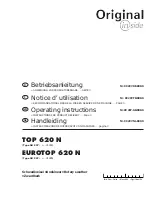
STEP 23
RD02C109
Place the boot (1) with wire stiffener and boot plate
installed, over the steering column. Partially install
the boot support washer (2). Install the turn signal
switch wiring harness through the protruding opening
in the boot (3).
STEP 24
RD02C105
Install the lower control housing assembly. Make sure
the alignment tab on the turn signal switch clamp is
located in the hole on the steering column collar.
Tighten the socket head cap screw for the turn signal
switch clamp.
1
1
2
2
1
3
Содержание T8010
Страница 22: ...Section 00 Chapter 1 January 2006 STANDARD TORQUE SPECIFICATION ...
Страница 28: ...Section 00 Chapter 2 January 2006 SAFETY GENERALINFORMATION MAINTENANCE SCHEDULE ...
Страница 35: ...Section 00 General Information Chapter 2 00 2 8 This Page Left Blank ...
Страница 36: ...Section 10 Chapter 1 January 2006 ENGINE REMOVAL AND INSTALLATION ...
Страница 37: ...Section 10 Engine Chapter 1 10 1 2 TABLE OF CONTENTS ENGINE REMOVAL 10 1 3 ENGINE INSTALLATION 10 1 10 ...
Страница 52: ...Section 10 Chapter 2 January 2006 FUEL TANK FUEL SENDER REMOVAL AND INSTALLATION ...
Страница 63: ...Section 10 Engine Chapter 2 10 2 12 ...
Страница 64: ...Section 10 Chapter 3 January 2006 HOOD REMOVAL INSTALLATION ...
Страница 65: ...Section 10 Engine Chapter 3 10 3 2 TABLE OF CONTENTS HOOD REMOVAL 10 3 3 HOOD INSTALLATION 10 3 5 ...
Страница 70: ...Section 10 Chapter 4 January 2006 COOLING SYSTEM MODULE REMOVAL AND INSTALLATION ...
Страница 80: ...Section 10 Chapter 5 January 2006 VISCOUS FAN DRIVE TEST ...
Страница 90: ...Section 21 Chapter 1 January 2006 POWERSHIFT TRANSMISSION SYSTEM How It Works and Troubleshooting ...
Страница 140: ...Section 21 Chapter 2 January 2006 FRONT FRAME TO SPEED TRANSMISSION SPLIT ...
Страница 151: ...Section 21 Transmission Drivelines Chapter 2 21 2 12 This Page Left Blank ...
Страница 152: ...Section 21 Chapter 3 January 2006 SPEED TO RANGE TRANSMISSION SPLIT ...
Страница 161: ...Section 21 Transmission Drivelines Chapter 3 10 This Page Left Blank ...
Страница 162: ...Section 21 Chapter 4 January 2006 SPEED TRANSMISSION ...
Страница 244: ...Section 21 Chapter 5 January 2006 RANGE TRANSMISSION TO REAR FRAME SPLIT ...
Страница 254: ...Section 21 Chapter 6 January 2006 RANGE TRANSMISSION ...
Страница 330: ...Section 21 Chapter 7 January 2006 TRANSMISSION CONTROL VALVES AND INCHING VALVE ...
Страница 351: ...Section 21 Transmission Drivelines Chapter 7 21 7 22 This Page Left Blank ...
Страница 352: ...Section 21 Chapter 8 January 2006 REAR FRAME ...
Страница 392: ...Section 21 Chapter 9 January 2006 HYDRAULIC PUMP DRIVE ...
Страница 404: ...Section 25 Chapter 1 January 2006 FRONT WHEEL DRIVE FWD CONTROL SYSTEM How It Works ...
Страница 407: ...Section 25 Four Wheel Drive Front Axle Chapter 1 25 1 4 RI02E086 1 FWD SOLENOID 2 POWERSHIFT VALVE RANGE 1 2 ...
Страница 409: ...Section 25 Four Wheel Drive Front Axle Chapter 1 25 1 6 RH05J060 1 FRONT WHEEL DRIVE FWD SWITCH 1 ...
Страница 416: ...Section 25 Chapter 2 January 2006 DIFFERENTIAL LOCK CONTROL SYSTEM How It Works ...
Страница 419: ...Section 25 Four Wheel Drive Front Axle Chapter 2 25 2 4 RI02E086 1 PTO DIFF LOCK VALVE 2 DIFF LOCK CLUTCH SOLENOID 1 2 ...
Страница 421: ...Section 25 Four Wheel Drive Front Axle Chapter 2 25 2 6 RD05J060 1 DIFFERENTIAL LOCK SWITCH 1 ...
Страница 431: ...Section 25 Four Wheel Drive Front Axle Chapter 2 25 2 16 This Page Left Blank ...
Страница 432: ...Section 25 Chapter 3 January 2006 FWD OUTPUT SHAFT ...
Страница 447: ...Section 25 Four Wheel Drive Front Axle Chapter 3 25 3 16 This Page Left Blank ...
Страница 448: ...Section 25 Chapter 4 January 2006 FWD DRIVE SHAFT ...
Страница 449: ...Section 25 Four Wheel Drive Front Axle Chapter 4 25 4 2 TABLE OF CONTENTS SPECIAL TORQUES 25 4 3 FWD DRIVE SHAFT 25 4 4 ...
Страница 455: ...Section 25 Four Wheel Drive Front Axle Chapter 4 25 4 8 ...
Страница 456: ...Section 25 Chapter 5 January 2006 SUSPENDED FWD AXLE SYSTEM How It Works and Troubleshooting ...
Страница 474: ...Section 25 Chapter 6 January 2006 SUSPENDED FWD AXLE REMOVAL ...
Страница 480: ...Section 25 Chapter 7 January 2006 SUPERSTEER AXLE REMOVAL AND INSTALLATION ...
Страница 489: ...Section 25 Four Wheel Drive Front Axle Chapter 7 25 7 10 ...
Страница 490: ...Section 25 Chapter 8 January 2006 LIMITED SLIP FWD DIFFERENTIAL ...
Страница 517: ...Section 25 Four Wheel Drive Front Axle Chapter 8 25 8 28 ...
Страница 518: ...Section 25 Chapter 9 January 2006 LOCKING FWD DIFFERENTIAL ...
Страница 546: ...Section 25 Chapter 10 January 2006 FWD PLANETARY HUB STEERING KNUCKLE AND AXLE DRIVE SHAFT ...
Страница 588: ...Section 25 Chapter 11 January 2006 SUSPENSION FWD AXLE ...
Страница 613: ...Section 25 Four Wheel Drive Front Axle Chapter 11 25 11 26 ...
Страница 614: ...Section 25 Chapter 12 January 2006 SUPERSTEER AXLE VERTICAL CONTROL LINKAGE ...
Страница 620: ...Section 27 Chapter 1 January 2006 REAR AXLE AND PLANETARIES ...
Страница 652: ...Section 31 Chapter 1 January 2006 POWER TAKE OFF CONTROL SYSTEM How it Works ...
Страница 656: ...Section 31 PTO Chapter 1 31 1 5 RD05J060 1 PTO CONTROL SWITCH 1 ...
Страница 670: ...Section 31 Chapter 2 January 2006 PTO CLUTCH ASSEMBLY Single Reversible and Dual Speed ...
Страница 684: ...Section 31 PTO Chapter 2 31 2 15 STEP 42 Remove bearing cones from each side of the bearing cage RD05D008 RD05D010 ...
Страница 715: ...Section 31 PTO Chapter 2 31 2 46 This Page Left Blank ...
Страница 716: ...Section 33 Chapter 1 January 2006 BRAKE VALVE ...
Страница 724: ...Section 33 Brakes Chapter 1 33 1 9 STEP 26 102RS5 Install the right side cover ...
Страница 725: ...Section 33 Brakes Chapter 1 33 1 10 ...
Страница 726: ...Section 33 Chapter 2 January 2006 BRAKE CYLINDERS ...
Страница 735: ...Section 33 Brakes Chapter 2 33 2 10 ...
Страница 738: ...Section 35 Chapter 1 January 2006 HOW TO READ SYMBOLS IN A HYDRAULIC SCHEMATIC ...
Страница 749: ...Section 35 Hydraulic Systems 3PT Chapter 1 35 1 12 NOTES ...
Страница 757: ...Section 35 Hydraulic Systems 3PT Chapter 1 35 1 20 ...
Страница 758: ...Section 35 Chapter 2 January 2006 HYDRAULIC SYSTEM HOW IT WORKS WITH TROUBLESHOOTING ...
Страница 807: ...Section 35 Hydraulic Systems 3PT Chapter 2 35 2 50 This Page Left Blank ...
Страница 808: ...Section 35 Chapter 3 January 2006 PTO AND DIFFERENTIAL LOCK VALVE ...
Страница 818: ...Section 35 Chapter 4 January 2006 REMOTE VALVE AND COUPLER SERVICE ...
Страница 832: ...Section 35 Chapter 5 January 2006 REMOTE HYDRAULIC SYSTEM How It Works and Troubleshooting ...
Страница 866: ...Section 35 Chapter 6 January 2006 PRIORITY AND REGULATOR VALVE ...
Страница 880: ...Section 35 Chapter 7 January 2006 CHARGE PUMP ...
Страница 884: ...Section 35 Chapter 8 January 2006 PFC PISTON PUMP ...
Страница 888: ...Section 35 Chapter 9 January 2006 HITCH SYSTEM How it Works ...
Страница 910: ...Section 35 Chapter 10 January 2006 HITCH CONTROL VALVE ...
Страница 921: ...Section 35 Hydraulic Systems 3PT Chapter 10 35 10 12 ...
Страница 922: ...Section 35 Chapter 11 January 2006 TRACTOR HITCH ...
Страница 949: ...Section 35 Hydraulic Systems 3PT Chapter 11 35 11 28 This Page Left Blank ...
Страница 950: ...Section 41 Chapter 1 January 2006 STEERING COLUMN AND STEERING HAND PUMP REMOVAL AND INSTALLATION ...
Страница 961: ...Section 41 Steering Chapter 1 41 1 12 ...
Страница 962: ...Section 41 Chapter 2 January 2006 WHEEL TOE IN SETTING SuperSteer FWD Axle ...
Страница 972: ...Section 50 Chapter 1 January 2006 AIR CONDITIONING SYSTEM Troubleshooting and Fault Codes ...
Страница 1061: ...Section 50 Climate Control Chapter 1 50 1 90 NOTES ...
Страница 1062: ...Section 50 Chapter 2 January 2006 AIR CONDITIONER SYSTEM SERVICE ...
Страница 1182: ...Section 55 Chapter 1 January 2006 ELECTRICAL SYSTEM How It Works And Troubleshooting ...
Страница 1189: ...Section 55 Electrical System Chapter 1 55 1 8 INSTRUMENTATION AND CONTROLS RD05J040 INSTRUMENTATION CLUSTER ...
Страница 1198: ...Section 55 Electrical System Chapter 1 55 1 17 ARMRST RIGHT HAND CONSOLE 1 ARMREST CONTROLLER 1 ...
Страница 1208: ...Section 55 Electrical System Chapter 1 55 1 27 RD06A178 UNDER HOOD 1 INTERMEDIATE STARTING RELAY 1 ...
Страница 1386: ...Section 55 Chapter 2 January 2006 INSTRUMENTATION CONTROLLER FAULT CODES ...
Страница 1419: ...Section 55 Electrical System Controller Chapter 2 55 2 34 ...
Страница 1420: ...Section 55 Chapter 3 January 2006 AUX HITCH PTO FAULT CODES TRACTOR MULTI FUNCTION TMF CONTROLLER ...
Страница 1528: ...Section 55 Chapter 4 January 2006 TRANSMISSION CONTROLLER FAULT CODES INCLUDES SUSPENDED AXLE ...
Страница 1605: ...Section 55 Electrical System Controller Chapter 4 55 4 78 ...
Страница 1606: ...Section 55 Chapter 5 January 2006 ARMREST CONTROLLER FAULT CODES ...
Страница 1645: ...Section 55 Electrical System Controller Chapter 5 55 5 40 ...
Страница 1646: ...Section 55 Chapter 6 January 2006 ELECTRONIC CONTROLLER CONFIGURATION CALIBRATION AND FAULT CODE RETRIEVAL ...
Страница 1722: ...Section 90 Chapter 1 January 2006 PEDAL AND PEDAL SWITCH ADJUSTMENTS ...
Страница 1726: ...Section 90 Chapter 2 January 2006 CAB RAISE REMOVAL AND INSTALLATION ...