Section 21 - Transmission, Drivelines - Chapter 8
21-8-38
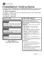
BEVEL PINION AND GEAR TOOTH CONTACT CHECK
STEP 160
t98215A
Adjust the ring and pinion backlash as follows:
1. Mount a dial indicator on the rear frame.
2. Position the dial indicator so that it contacts one
tooth on the ring gear. Do not move the pinion
gear.
3. Rotate the ring gear in either the forward or
reverse direction to achieve full contact with the
pinion gear.
IMPORTANT: Pinion shaft must be held in place so
it will not move.
4. Zero the dial indicator.
5. Rotate the ring gear in the opposite direction to
achieve full contact with the pinion gear in the
opposite direction.
IMPORTANT: Pinion shaft must be held in place so
it will not move.
6. Record the dial indicator reading.
7. The dial indicator reading is the ring and pinion
gear backlash. The backlash must be between
0.179 to 0.279 mm (0.007 to 0.11 inch).
8. To adjust the ring and pinion gear backlash,
move shims from one side of the differential to
the other. Moving a 0.254 mm (0.010 inch) shim
from one side to the other will change the
backlash approximately 0.169 mm (0.0067 inch).
STEP 161
Put Prussian Blue or red lead onto the convex side of
the gear teeth. Turn the pinion several revolutions in
the forward (clockwise) direction, while applying a
braking force on the gear, to determine the contact
pattern. See the contact patterns in the following
illustrations.
NOTE: The contact pattern of the gear teeth that are
shown are approximate shapes. The gear tooth
contact patterns can change from the illustrations.
Any shape or pattern (L-type, band, C-type, triangle,
etc.) is acceptable if it is tapering off from toe to heel
and falls into the contact area shown. The tooth
contact pattern can change in a used gear set
because of wear of the parts. Try to get a contact
pattern that is similiar to the illustrations to get the
best results.
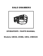
64L8
Correct Tooth Contact Pattern
Correct adjustment is made when the pattern of the
tooth contact area (both horizontal and vertical) is as
shown.
66L8
Pattern A
The pinion is out too far. Remove approximately 0.10
mm (0.005 inch) of shim material that was installed in
Step 75.
Содержание T8010
Страница 22: ...Section 00 Chapter 1 January 2006 STANDARD TORQUE SPECIFICATION ...
Страница 28: ...Section 00 Chapter 2 January 2006 SAFETY GENERALINFORMATION MAINTENANCE SCHEDULE ...
Страница 35: ...Section 00 General Information Chapter 2 00 2 8 This Page Left Blank ...
Страница 36: ...Section 10 Chapter 1 January 2006 ENGINE REMOVAL AND INSTALLATION ...
Страница 37: ...Section 10 Engine Chapter 1 10 1 2 TABLE OF CONTENTS ENGINE REMOVAL 10 1 3 ENGINE INSTALLATION 10 1 10 ...
Страница 52: ...Section 10 Chapter 2 January 2006 FUEL TANK FUEL SENDER REMOVAL AND INSTALLATION ...
Страница 63: ...Section 10 Engine Chapter 2 10 2 12 ...
Страница 64: ...Section 10 Chapter 3 January 2006 HOOD REMOVAL INSTALLATION ...
Страница 65: ...Section 10 Engine Chapter 3 10 3 2 TABLE OF CONTENTS HOOD REMOVAL 10 3 3 HOOD INSTALLATION 10 3 5 ...
Страница 70: ...Section 10 Chapter 4 January 2006 COOLING SYSTEM MODULE REMOVAL AND INSTALLATION ...
Страница 80: ...Section 10 Chapter 5 January 2006 VISCOUS FAN DRIVE TEST ...
Страница 90: ...Section 21 Chapter 1 January 2006 POWERSHIFT TRANSMISSION SYSTEM How It Works and Troubleshooting ...
Страница 140: ...Section 21 Chapter 2 January 2006 FRONT FRAME TO SPEED TRANSMISSION SPLIT ...
Страница 151: ...Section 21 Transmission Drivelines Chapter 2 21 2 12 This Page Left Blank ...
Страница 152: ...Section 21 Chapter 3 January 2006 SPEED TO RANGE TRANSMISSION SPLIT ...
Страница 161: ...Section 21 Transmission Drivelines Chapter 3 10 This Page Left Blank ...
Страница 162: ...Section 21 Chapter 4 January 2006 SPEED TRANSMISSION ...
Страница 244: ...Section 21 Chapter 5 January 2006 RANGE TRANSMISSION TO REAR FRAME SPLIT ...
Страница 254: ...Section 21 Chapter 6 January 2006 RANGE TRANSMISSION ...
Страница 330: ...Section 21 Chapter 7 January 2006 TRANSMISSION CONTROL VALVES AND INCHING VALVE ...
Страница 351: ...Section 21 Transmission Drivelines Chapter 7 21 7 22 This Page Left Blank ...
Страница 352: ...Section 21 Chapter 8 January 2006 REAR FRAME ...
Страница 392: ...Section 21 Chapter 9 January 2006 HYDRAULIC PUMP DRIVE ...
Страница 404: ...Section 25 Chapter 1 January 2006 FRONT WHEEL DRIVE FWD CONTROL SYSTEM How It Works ...
Страница 407: ...Section 25 Four Wheel Drive Front Axle Chapter 1 25 1 4 RI02E086 1 FWD SOLENOID 2 POWERSHIFT VALVE RANGE 1 2 ...
Страница 409: ...Section 25 Four Wheel Drive Front Axle Chapter 1 25 1 6 RH05J060 1 FRONT WHEEL DRIVE FWD SWITCH 1 ...
Страница 416: ...Section 25 Chapter 2 January 2006 DIFFERENTIAL LOCK CONTROL SYSTEM How It Works ...
Страница 419: ...Section 25 Four Wheel Drive Front Axle Chapter 2 25 2 4 RI02E086 1 PTO DIFF LOCK VALVE 2 DIFF LOCK CLUTCH SOLENOID 1 2 ...
Страница 421: ...Section 25 Four Wheel Drive Front Axle Chapter 2 25 2 6 RD05J060 1 DIFFERENTIAL LOCK SWITCH 1 ...
Страница 431: ...Section 25 Four Wheel Drive Front Axle Chapter 2 25 2 16 This Page Left Blank ...
Страница 432: ...Section 25 Chapter 3 January 2006 FWD OUTPUT SHAFT ...
Страница 447: ...Section 25 Four Wheel Drive Front Axle Chapter 3 25 3 16 This Page Left Blank ...
Страница 448: ...Section 25 Chapter 4 January 2006 FWD DRIVE SHAFT ...
Страница 449: ...Section 25 Four Wheel Drive Front Axle Chapter 4 25 4 2 TABLE OF CONTENTS SPECIAL TORQUES 25 4 3 FWD DRIVE SHAFT 25 4 4 ...
Страница 455: ...Section 25 Four Wheel Drive Front Axle Chapter 4 25 4 8 ...
Страница 456: ...Section 25 Chapter 5 January 2006 SUSPENDED FWD AXLE SYSTEM How It Works and Troubleshooting ...
Страница 474: ...Section 25 Chapter 6 January 2006 SUSPENDED FWD AXLE REMOVAL ...
Страница 480: ...Section 25 Chapter 7 January 2006 SUPERSTEER AXLE REMOVAL AND INSTALLATION ...
Страница 489: ...Section 25 Four Wheel Drive Front Axle Chapter 7 25 7 10 ...
Страница 490: ...Section 25 Chapter 8 January 2006 LIMITED SLIP FWD DIFFERENTIAL ...
Страница 517: ...Section 25 Four Wheel Drive Front Axle Chapter 8 25 8 28 ...
Страница 518: ...Section 25 Chapter 9 January 2006 LOCKING FWD DIFFERENTIAL ...
Страница 546: ...Section 25 Chapter 10 January 2006 FWD PLANETARY HUB STEERING KNUCKLE AND AXLE DRIVE SHAFT ...
Страница 588: ...Section 25 Chapter 11 January 2006 SUSPENSION FWD AXLE ...
Страница 613: ...Section 25 Four Wheel Drive Front Axle Chapter 11 25 11 26 ...
Страница 614: ...Section 25 Chapter 12 January 2006 SUPERSTEER AXLE VERTICAL CONTROL LINKAGE ...
Страница 620: ...Section 27 Chapter 1 January 2006 REAR AXLE AND PLANETARIES ...
Страница 652: ...Section 31 Chapter 1 January 2006 POWER TAKE OFF CONTROL SYSTEM How it Works ...
Страница 656: ...Section 31 PTO Chapter 1 31 1 5 RD05J060 1 PTO CONTROL SWITCH 1 ...
Страница 670: ...Section 31 Chapter 2 January 2006 PTO CLUTCH ASSEMBLY Single Reversible and Dual Speed ...
Страница 684: ...Section 31 PTO Chapter 2 31 2 15 STEP 42 Remove bearing cones from each side of the bearing cage RD05D008 RD05D010 ...
Страница 715: ...Section 31 PTO Chapter 2 31 2 46 This Page Left Blank ...
Страница 716: ...Section 33 Chapter 1 January 2006 BRAKE VALVE ...
Страница 724: ...Section 33 Brakes Chapter 1 33 1 9 STEP 26 102RS5 Install the right side cover ...
Страница 725: ...Section 33 Brakes Chapter 1 33 1 10 ...
Страница 726: ...Section 33 Chapter 2 January 2006 BRAKE CYLINDERS ...
Страница 735: ...Section 33 Brakes Chapter 2 33 2 10 ...
Страница 738: ...Section 35 Chapter 1 January 2006 HOW TO READ SYMBOLS IN A HYDRAULIC SCHEMATIC ...
Страница 749: ...Section 35 Hydraulic Systems 3PT Chapter 1 35 1 12 NOTES ...
Страница 757: ...Section 35 Hydraulic Systems 3PT Chapter 1 35 1 20 ...
Страница 758: ...Section 35 Chapter 2 January 2006 HYDRAULIC SYSTEM HOW IT WORKS WITH TROUBLESHOOTING ...
Страница 807: ...Section 35 Hydraulic Systems 3PT Chapter 2 35 2 50 This Page Left Blank ...
Страница 808: ...Section 35 Chapter 3 January 2006 PTO AND DIFFERENTIAL LOCK VALVE ...
Страница 818: ...Section 35 Chapter 4 January 2006 REMOTE VALVE AND COUPLER SERVICE ...
Страница 832: ...Section 35 Chapter 5 January 2006 REMOTE HYDRAULIC SYSTEM How It Works and Troubleshooting ...
Страница 866: ...Section 35 Chapter 6 January 2006 PRIORITY AND REGULATOR VALVE ...
Страница 880: ...Section 35 Chapter 7 January 2006 CHARGE PUMP ...
Страница 884: ...Section 35 Chapter 8 January 2006 PFC PISTON PUMP ...
Страница 888: ...Section 35 Chapter 9 January 2006 HITCH SYSTEM How it Works ...
Страница 910: ...Section 35 Chapter 10 January 2006 HITCH CONTROL VALVE ...
Страница 921: ...Section 35 Hydraulic Systems 3PT Chapter 10 35 10 12 ...
Страница 922: ...Section 35 Chapter 11 January 2006 TRACTOR HITCH ...
Страница 949: ...Section 35 Hydraulic Systems 3PT Chapter 11 35 11 28 This Page Left Blank ...
Страница 950: ...Section 41 Chapter 1 January 2006 STEERING COLUMN AND STEERING HAND PUMP REMOVAL AND INSTALLATION ...
Страница 961: ...Section 41 Steering Chapter 1 41 1 12 ...
Страница 962: ...Section 41 Chapter 2 January 2006 WHEEL TOE IN SETTING SuperSteer FWD Axle ...
Страница 972: ...Section 50 Chapter 1 January 2006 AIR CONDITIONING SYSTEM Troubleshooting and Fault Codes ...
Страница 1061: ...Section 50 Climate Control Chapter 1 50 1 90 NOTES ...
Страница 1062: ...Section 50 Chapter 2 January 2006 AIR CONDITIONER SYSTEM SERVICE ...
Страница 1182: ...Section 55 Chapter 1 January 2006 ELECTRICAL SYSTEM How It Works And Troubleshooting ...
Страница 1189: ...Section 55 Electrical System Chapter 1 55 1 8 INSTRUMENTATION AND CONTROLS RD05J040 INSTRUMENTATION CLUSTER ...
Страница 1198: ...Section 55 Electrical System Chapter 1 55 1 17 ARMRST RIGHT HAND CONSOLE 1 ARMREST CONTROLLER 1 ...
Страница 1208: ...Section 55 Electrical System Chapter 1 55 1 27 RD06A178 UNDER HOOD 1 INTERMEDIATE STARTING RELAY 1 ...
Страница 1386: ...Section 55 Chapter 2 January 2006 INSTRUMENTATION CONTROLLER FAULT CODES ...
Страница 1419: ...Section 55 Electrical System Controller Chapter 2 55 2 34 ...
Страница 1420: ...Section 55 Chapter 3 January 2006 AUX HITCH PTO FAULT CODES TRACTOR MULTI FUNCTION TMF CONTROLLER ...
Страница 1528: ...Section 55 Chapter 4 January 2006 TRANSMISSION CONTROLLER FAULT CODES INCLUDES SUSPENDED AXLE ...
Страница 1605: ...Section 55 Electrical System Controller Chapter 4 55 4 78 ...
Страница 1606: ...Section 55 Chapter 5 January 2006 ARMREST CONTROLLER FAULT CODES ...
Страница 1645: ...Section 55 Electrical System Controller Chapter 5 55 5 40 ...
Страница 1646: ...Section 55 Chapter 6 January 2006 ELECTRONIC CONTROLLER CONFIGURATION CALIBRATION AND FAULT CODE RETRIEVAL ...
Страница 1722: ...Section 90 Chapter 1 January 2006 PEDAL AND PEDAL SWITCH ADJUSTMENTS ...
Страница 1726: ...Section 90 Chapter 2 January 2006 CAB RAISE REMOVAL AND INSTALLATION ...